
Opportunistic power management for managing intermittent power available to data processing device having semi-non-volatile memory or non-volatile memory

a data processing device and intermittent power management technology, applied in the field of power management techniques in data processing systems, can solve the problems of long-life batteries contributing much weight and bulk, intermittent power often not remaining available, and inherently unpredictable intermittent sources

Active Publication Date: 2016-12-29
INTEL CORP
View PDF4 Cites 27 Cited by
  • Summary
  • Abstract
  • Description
  • Claims
  • Application Information

AI Technical Summary

Benefits of technology

This patent describes a way to manage power to improve performance and reduce energy consumption in applications and systems like IoT devices. The techniques include opportunistic energy management and power optimization, which can be used with systems that have internal memory. These techniques help avoid external storage energy consumption, leading to improved management and reduced device size. Overall, the patent provides a valuable tool for reducing energy consumption and improving performance in resource-constrained systems.

Problems solved by technology

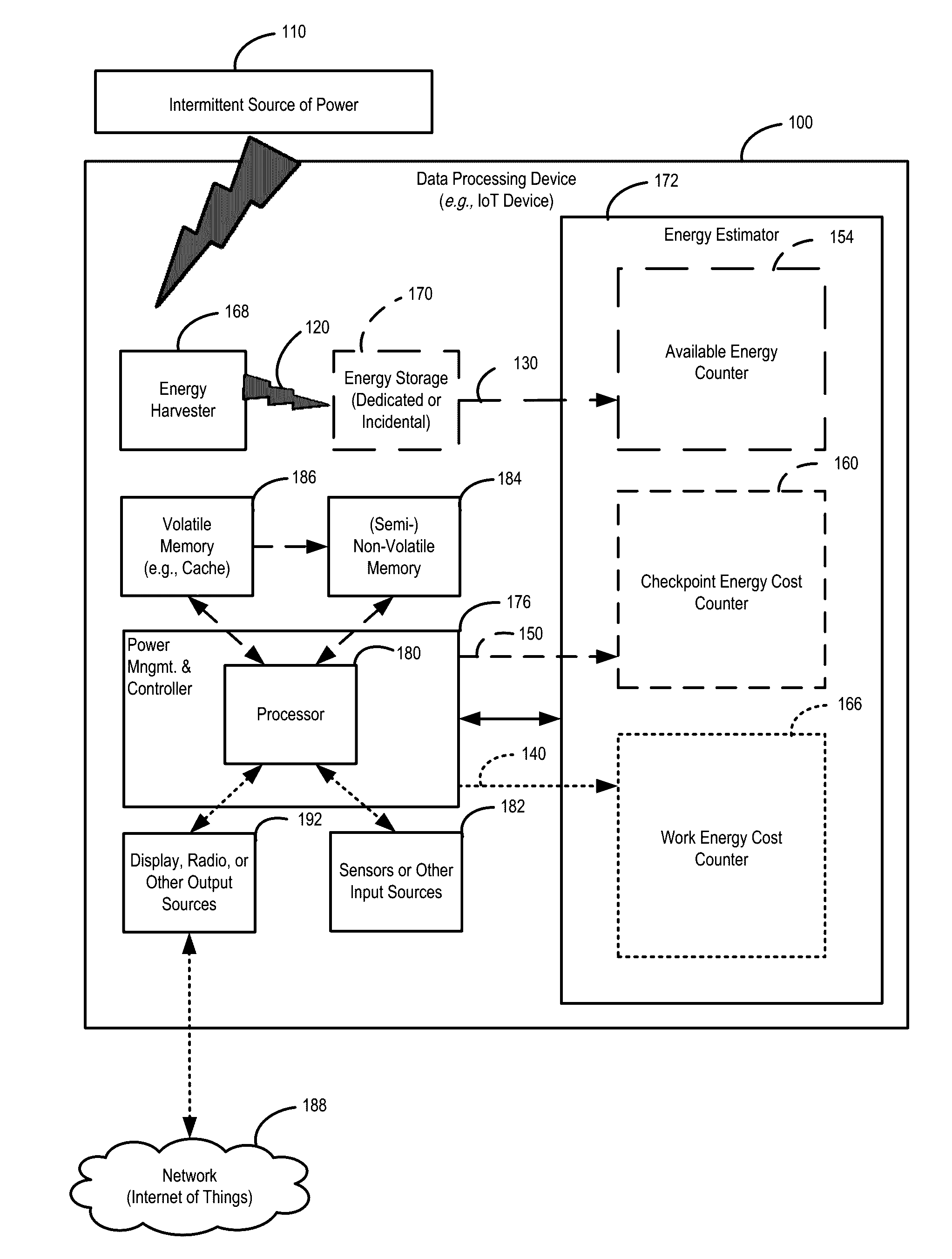
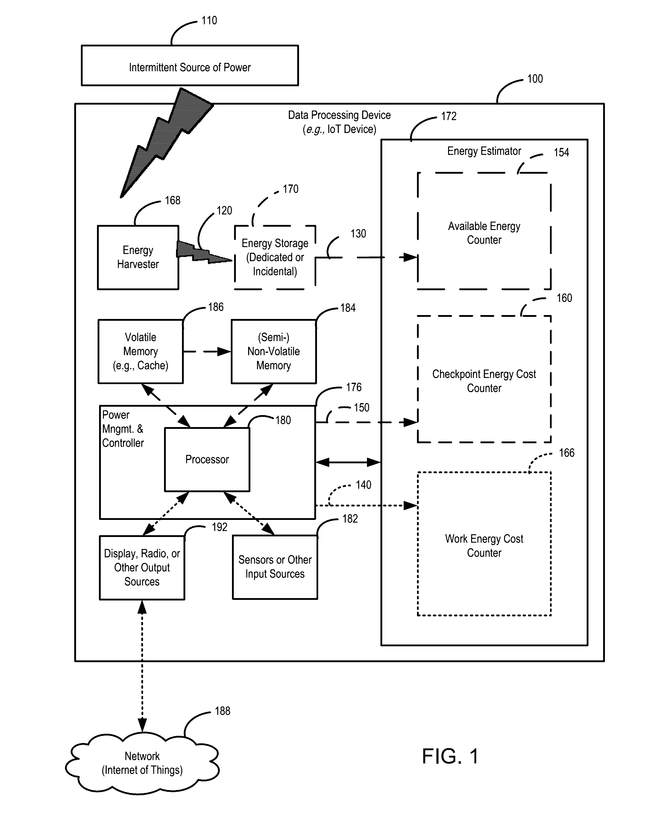
In contrast, embedded computing systems—such as smart monitoring data processing devices connected to an Internet of Things (IoT) network of other IoT devices—have specific challenges concerning intermittent availability of power, and managing data processing operations in view of diminishing availability of energy.
Intermittent power often does not remain available.
Although batteries and other types of energy storage used in conjunction with energy harvesting may extend the duration of the energy available, an intermittent source of power is still inherently unpredictable—a solar-powered device might be put in a drawer for months.
For example, some IoT devices include long-life batteries contributing much weight and bulk, which are undesirable attributes of wearables and other types of small sensor devices.
Thus, current small embedded systems using the paradigm of power management for general-purpose computing systems do not effectively manage computing and energy resources in the context of intermittent power for applications having predictable energy use.

Method used


Image

  • Opportunistic power management for managing intermittent power available to data processing device having semi-non-volatile memory or non-volatile memory
  • Opportunistic power management for managing intermittent power available to data processing device having semi-non-volatile memory or non-volatile memory
  • Opportunistic power management for managing intermittent power available to data processing device having semi-non-volatile memory or non-volatile memory

Examples


case examples

OVERVIEW OF USE CASE EXAMPLES

[0074]Two example use cases are set forth as follows. Use case example no. 1 is fairly self-contained. It shows power management integrated with all device activity. This can be thought of as a tiny device or embedded use case (e.g., consistent with the data processing device 100, where simplicity is an important consideration). Use case example no. 2 describes a power management routine but not the application code because the application is ordinary code and need not be coded in any particular way to take advantage of power management. This latter use case example assumes hardware support in the form of a cache and a count of the number of modified cache lines. The second use case example may be thought of as a general-purpose device use case (e.g., for the computer system 500). In short, use case example no. 1 includes all parts in the sense that it is a full example of the system, whereas use case example no. 2 shows the energy management control loo...

use case example 1

[0075]This example could be hardware, software, or some combination of the two. If viewed as software, then instruction code (software) includes energy decisions explicitly—that is, pre-existing software may be tailored to include the energy decisions. The example assumes the following components: a radio, a temperature sensor, a non-volatile queue, and a volatile queue.

[0076]The energy consumed by each component is as follows, in the order low (least energy) to high (most energy): push (or pop, i.e., push / op) from volatile queue—assumed to have zero energy cost to simplify the example; push / pop from non-volatile queue—assumed to have a zero energy cost to simplify the example; read from temperature sensor; keep data in volatile memory (Le., storage or scrubbing cost); and transmit temperature sample on the radio. All other energy costs are assumed to be zero to simplify the example. In a practical system, there are other components that use energy, such as a so-called data processi...

use case example 2

[0097]In this example, there is a CPU (core) with a cache and memory (see, e.g., FIG. 5). The CPU may be running any program. The cache is volatile memory; the main memory is (semi-)NVM. Work advances fastest and most efficiently when it can write to the cache without writing to the main memory. When energy runs low, modified lines in the cache are written back to the main memory. Once all cache lines are written to memory, this checkpoints the progress so far. Power can be removed and reapplied and execution may resume. The checkpoint energy needed goes up according to the number of dirty cache lines,

[0098]Also, in this example, the application code is not shown. This is because the example expects the application to be written normally, without consideration of energy management. This demonstrates that the example is applicable for management of any code, without modification of the code so that it will work in an opportunistic power management deployment. An obstacle with prior a...


PUM


Abstract

A data processing device is configured to deploy, in response to an intermittent source of power, opportunistic power management strategies to manage harvested energy based on an expected amount of energy available to the data processing device and on expected energy expenditures defined by data processing and memory content control writing performed by the data processing device.

Description

TECHNICAL FIELD[0001]The present disclosure relates generally to power management techniques in data processing systems, and more particularly to power management techniques for systems powered by harvesting energy from intermittent sources of power.BACKGROUND INFORMATION[0002]Although power management has been an active field of research, the research effort has generally focused on system-level power management in general-purpose computing system paradigms premised on the availability of an uninterrupted supply of power. In contrast, embedded computing systems—such as smart monitoring data processing devices connected to an Internet of Things (IoT) network of other IoT devices—have specific challenges concerning intermittent availability of power, and managing data processing operations in view of diminishing availability of energy. For example, some IoT devices use energy harvesting, in which one or more of ambient heat, motion, or radio-frequency energy are used as an intermitte...

Claims


Application Information

Patent Timeline
IPC IPC(8): G06F1/32
CPCG06F1/3275G06F1/3287G06F1/263G06F1/30G06F1/3212G06F1/3246Y02D10/00
Inventor NAEIMI, HELIAKEPPEL, DAVID
Owner INTEL CORP
Learn More