Energy based devices and methods for treatment of anatomic tissue defects

a technology of anatomic tissue and energy based devices, applied in the field of medical devices and methods, can solve the problems of complications high cost and potential side effects of such a procedure, and the risk of another stroke of patients with cryptogenic stroke, etc., to achieve the effect of promoting and enhancing the collapsibility of the electrod

Active Publication Date: 2007-12-13
TERUMO KK
View PDF20 Cites 125 Cited by
  • Summary
  • Abstract
  • Description
  • Claims
  • Application Information

AI Technical Summary

Benefits of technology

[0015] In some embodiments, the apparatus also includes a sheath disposed over at least part of the catheter body and having a proximal end and a distal end. In such embodiments, the energy transmission member and the housing are collapsible and axially movable relative to the sheath, from a collapsed position within the sheath to an expanded position beyond the distal end of the sheath. Optionally, the sheath may include a bend, closer to its distal end than its proximal end. In some embodiments, the catheter body also includes a bend, closer to its distal end than a proximal end of the sheath. In such embodiments, the catheter body bend and the sheath bend allow a user to change an angle of orientation of the energy transmission member and the housing by moving the catheter body relative to the sheath. Optionally, the sheath may also include a stretchable distal end for facilitating movement of the housing and the energy transmission member from the expanded configuration to the collapsed configuration within the sheath.
[0021] In some embodiments, the catheter device further includes an irrigation tube extending through the catheter body and having a distal aperture disposed within the housing and a vacuum tube extending through the catheter body and having a distal aperture disposed within the housing. In one embodiment, an inner surface of the housing includes a plurality of ridges and valleys forming channels to direct irrigation fluid from the irrigation tube distal aperture toward the tissues and subsequently toward the vacuum tube distal aperture. The inner surface may optionally further include an irrigation fluid blocking surface feature to help direct fluid forward and away from the irrigation tube distal aperture. In some embodiments, the irrigation tube is adapted to allow passage of a guidewire therethrough.
[0023] In some embodiments, the planar surface electrode includes an outer rim extending at least partially around an outer circumference of the electrode and a plurality of metallic struts formed in a pattern within the outer rim. In one embodiment, the rim is discontinuous, thus enhancing collapsibility of the electrode. In other embodiments, the rim includes one or more inward bends directed toward the struts, the inward bends adapted to promote collapsibility of the electrode. In some embodiments, some of the struts are attached to other struts as well as to the outer rim. In other embodiments, the struts are attached only to the outer rim and not to one another. In other embodiments, the struts are not attached at all to the outer rim, and may be attached to the housing through the material of the housing or other structure. The pattern of struts may include at least one area of more closely positioned struts relative to another area of less closely positioned struts, such that different areas of the electrode provide different amounts of energy transmission to the tissues. Alternatively or additionally, the pattern of struts may include at least one area of thicker struts relative to another area of thinner struts, such that different areas of the electrode provide different amounts of energy transmission to the tissues.
[0024] In some embodiments, the pattern of struts includes at least one fold line along which the electrode folds to allow the electrode to collapse. In some embodiments, the struts are attached asymmetrically to the outer rim such that a first half of the housing and electrode folds into a second half of the housing and electrode when the housing and electrode assume their collapsed configurations. For example, in some embodiments, the struts are attached to the outer rim at between 8 and 16 attachment points to enhance collapsibility of the electrode.
[0026] In various embodiments, an electrode may include any of a number of additional features. For example, in some embodiments, the electrode further comprises at least one guidewire aperture to allow passage of a guidewire through the electrode. The guidewire aperture may be disposed along the electrode in an offset position to facilitate positioning of the electrode over the anatomic defect. Some embodiments include two offset guidewire apertures for facilitating positioning of the electrode over the anatomic defect. Some embodiments further include a thermocouple attached to the electrode.
[0033] The energy applied to the tissues may include, but is not limited to, radiofrequency, microwave, ultrasound, laser, heat and / or cryogenic energy. In some embodiments, the energy is applied at different levels to different areas of tissue via the energy transmission member. For example, the different levels of energy may be applied via different densities of material comprising the energy transmission member. In other embodiments, the different levels of energy are applied via multiple energy delivery devices coupled with the energy transmission member at different regions of the ETM. In addition, in some embodiments it may be advantageous to heat the electrode prior to applying it to tissue, to facilitate the application of higher temperatures to the surface of the defect to be treated, as in direct heating versus use of RF, which relies on conductive or inductive heating of tissue at some depth below the surface.

Problems solved by technology

It has been estimated that patients with PFOs who have already had cryptogenic strokes may have a risk of having another stroke.
The cost and potential side-effects and complications of such a procedure must be low, however, since the event rate due to PFOs is relatively low.
Currently available interventional therapies for defect closure are generally fairly invasive and / or have potential drawbacks.
Performing open heart surgery purely to close an asymptomatic PFO or even a very small ASD, however, would be very hard to justify.
Although available devices may work well in some cases, they also face a number of challenges.
Relatively frequent causes of complications include, for example, improper deployment, device embolization into the circulation and device breakage.
In some instances, a deployed device does not heal into the septal wall completely, leaving an exposed tissue which may itself be a nidus for thrombus formation.
Furthermore, currently available devices are generally complex and expensive to manufacture, making their use for prophylactic treatment of PFO and other defects impractical.
None of these disclosures, however, show methods or apparatus suitable for positioning the tissues of an anatomic defect for welding or for delivering the energy to an anatomic defect to be welded.
The devices and methods described, however, cause trauma to PFO tissues to hopefully eventually cause scar tissue formation which will close the PFO.
Frequently, scar tissue may fail to form or may form incompletely, resulting in a still patent PFO.
In addition to PFO, a number of other anatomic tissue defects, such as other ASDs, ventricular septal defects (VSDs), patent ductus arteriosis (PDA), aneurysms and other blood vessel wall defects, atrial appendages and other naturally occurring cavities within which clot can form, and the like cause a number of different health problems (note that the term “defect” may include a naturally occurring structure that results a potential health risk such as the clot forming in the atrial appendage).

Method used


Image

  • Energy based devices and methods for treatment of anatomic tissue defects
  • Energy based devices and methods for treatment of anatomic tissue defects
  • Energy based devices and methods for treatment of anatomic tissue defects

Examples


Embodiment Construction

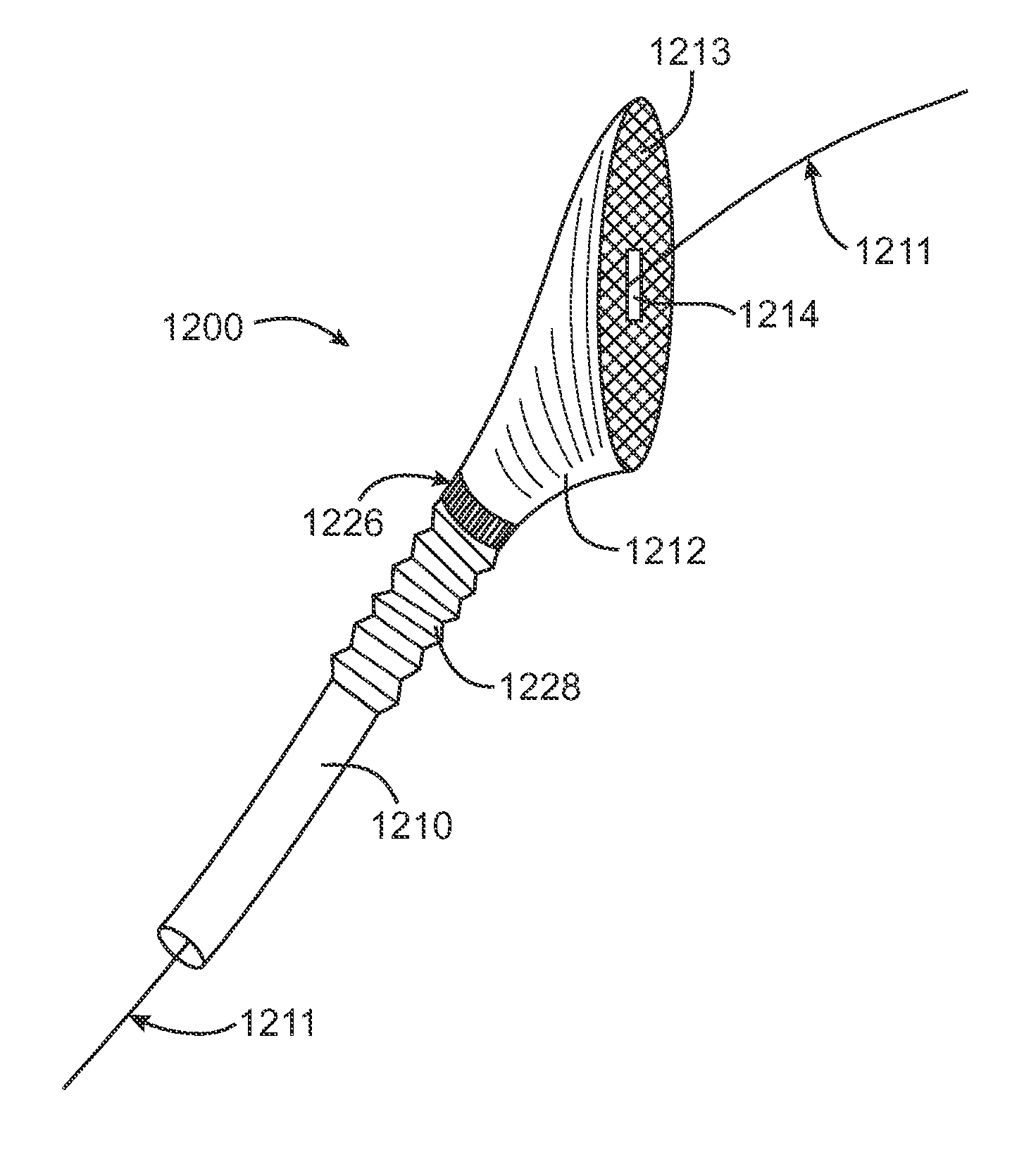
[0076] Devices and methods of the present invention generally provide for treatment of anatomic defects in human tissue, such as patent foramen ovale (PFO), atrial septal defect, ventricular septal defect, left atrial appendage (LAA), patent ductus arteriosis, vessel wall defects and / or the like through application of energy. In addition, electrophysiological defects, such as atrial fibrillation, supraventricular tachacardia (SVT), atrial flutter, A-V node re-entry, and Wolf Parkinson White syndrome, may be treated using various embodiments of the present invention. Therefore, although the following descriptions and the referenced drawing figures focus primarily on treatment of PFO, any other suitable tissue defects, such as but not limited to those just listed, may be treated in various embodiments.

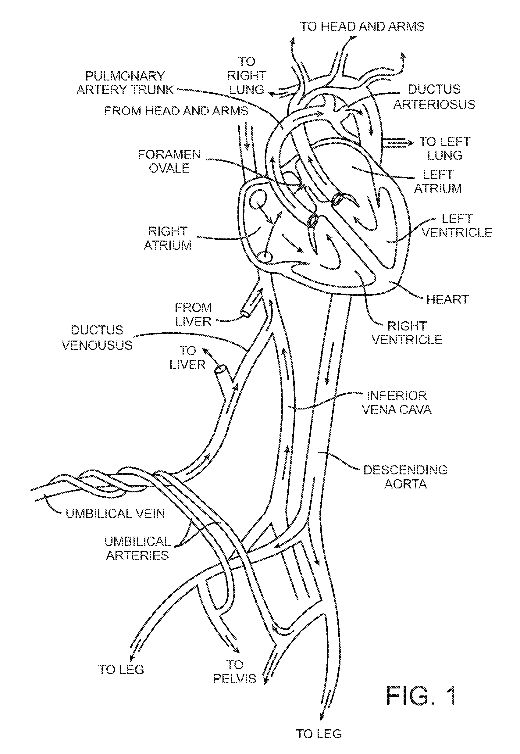
[0077] As mentioned in the background section above, FIG. 1 is a diagram of the fetal circulation. The foramen ovale is shown, with an arrow demonstrating that blood passes from the rig...


PUM


Abstract

Methods for treating anatomic tissue defects such as patent foramen ovale (PFO) generally involve positioning a distal end of an elongate catheter device at the site of the anatomic defect, exposing an expandable housing and energy transmission member out of the distal end of the catheter device, engaging the housing with tissues at the site of the anatomic defect, applying suction to the tissues via the housing to bring the tissues together; and applying energy to the tissues with the energy transmission member to substantially close the anatomic defect acutely. Apparatus generally include an elongate catheter body, a housing extending from a distal end of the catheter body for engaging tissues at the site of the anatomic defect, and an energy transmission member adjacent a distal end of the housing, the energy transmission member having at least one substantially planar surface.

Description

CROSS-REFERENCES TO RELATED APPLICATIONS [0001] This application is a divisional of U.S. patent application Ser. No. 10 / 952,492 (Attorney Docket No.: 022128-000220US), filed Sep. 27, 2004, which is related to U.S. patent application Ser. No. 10 / 873,348 (Attorney Docket No. 022128-000210US), filed Jun. 21, 2004, which is a continuation-in-part of U.S. patent application Ser. No. 10 / 679,245 (Attorney Docket No. 022128-000200US), filed Oct. 2, 2003, which claims priority to U.S. Provisional Patent Application Nos. 60 / 458,854 (Attorney Docket No. 022128-000100US), filed on Mar. 27, 2003; 60 / 478,035 (Attorney Docket No. 022128-00011US), filed on Jun. 11, 2003, and 60 / 490,082 (Attorney Docket No. 022128-000120US), filed on Jul. 24, 2003. The full disclosures of all of the above-listed patent applications are hereby incorporated by reference.BACKGROUND OF THE INVENTION [0002] The invention generally relates to medical devices and methods. More specifically, the invention relates to energy ...

Claims


Application Information

Patent Timeline
Patent Type & Authority Applications(United States)
IPC IPC(8): A61B18/18
CPCA61B18/1492A61B2017/00575A61B2018/00351A61B2018/00291A61B2018/00214A61M25/0068
Inventor MALECKI, WILLIAMFRANCIS, DANHORNE, KENNETHDEEM, MARK E.GIFFORD, HANSONALEJANDRO, JOSE
Owner TERUMO KK
Why Eureka
Try Eureka