
Camera calibration device, camera calibration method, and camera calibration program

Inactive Publication Date: 2016-12-29
KK TOPCON
View PDF3 Cites 4 Cited by
  • Summary
  • Abstract
  • Description
  • Claims
  • Application Information

AI Technical Summary

Benefits of technology

[0006]For the calibration of a camera, dedicated control points must be prepared, and the work for the calibration is complicated. In view of these circumstances, an object of the present invention is to provide a technique for easily performing calibration of a camera by using a MMS.
[0008]According to the first aspect of the present invention, by using the sun, of which the position on the celestial sphere surface can be precisely calculated, as a control point, calibration is performed for calculating the attitude of the camera. When the position of the sun in the image that is photographed by the camera is calculated from the orbital information of the sun, information of the attitude of the camera (direction in which the camera faces) is used. Therefore, when the attitude information of the camera contains uncertainties, an estimated position of the sun in the image, which is calculated from the attitude information, does not correspond to the observed position of the sun in the image. Accordingly, by searching parameters, which determine the attitude of the camera, so as to eliminate the difference between the estimated position and the observed position in the image, the attitude of the camera can be precisely calculated.
[0013]According to the present invention, a technique for easily performing the calibration of a camera by using the MMS is provided.

Problems solved by technology

For the calibration of a camera, dedicated control points must be prepared, and the work for the calibration is complicated.

Method used


Image

  • Camera calibration device, camera calibration method, and camera calibration program
  • Camera calibration device, camera calibration method, and camera calibration program
  • Camera calibration device, camera calibration method, and camera calibration program

Examples


example of processing

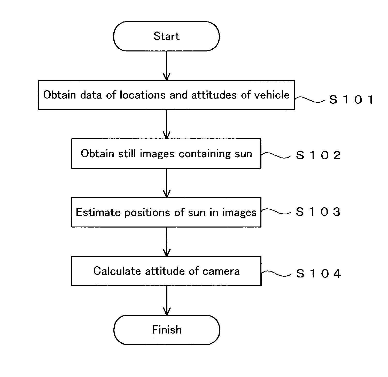
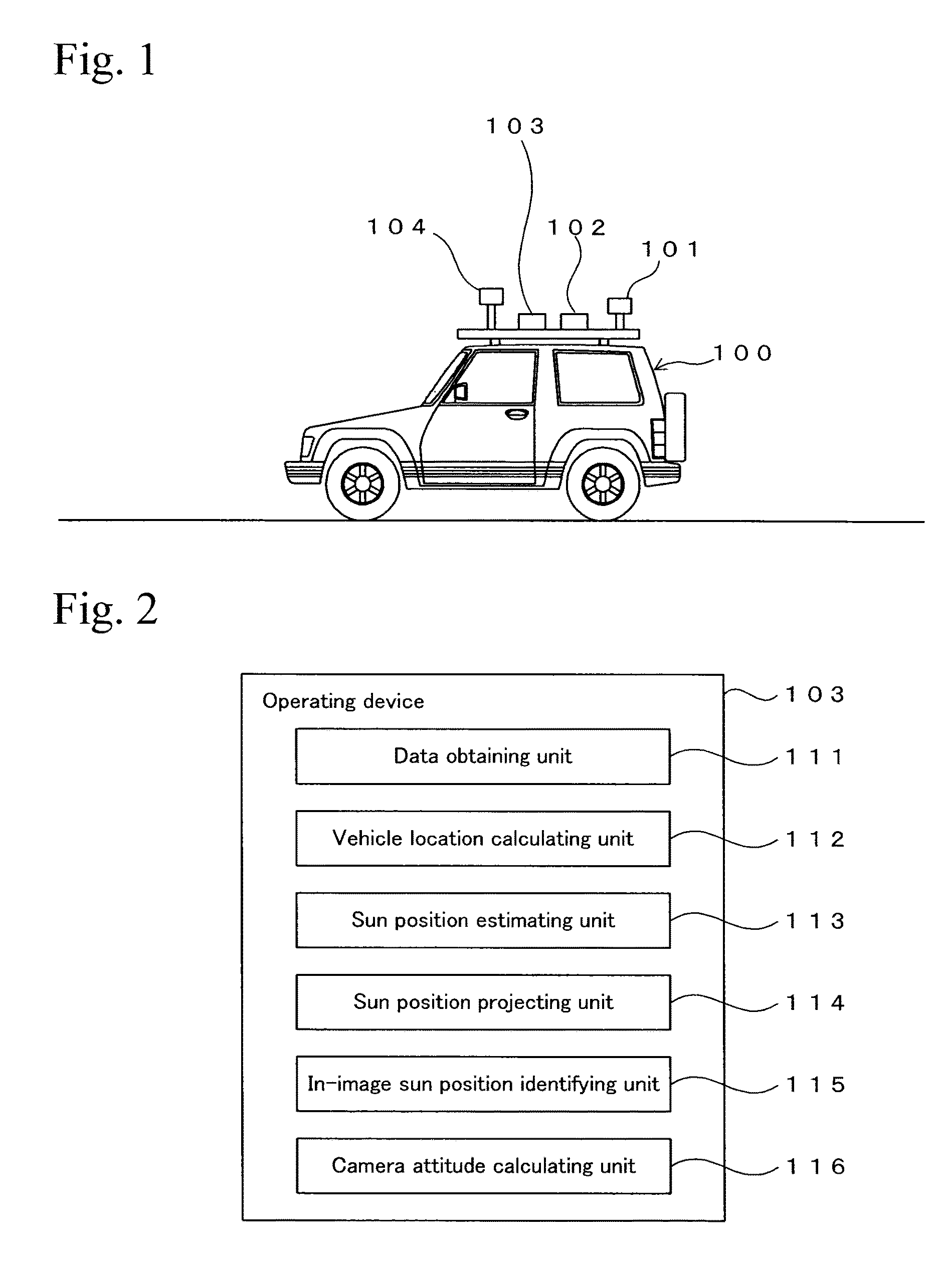
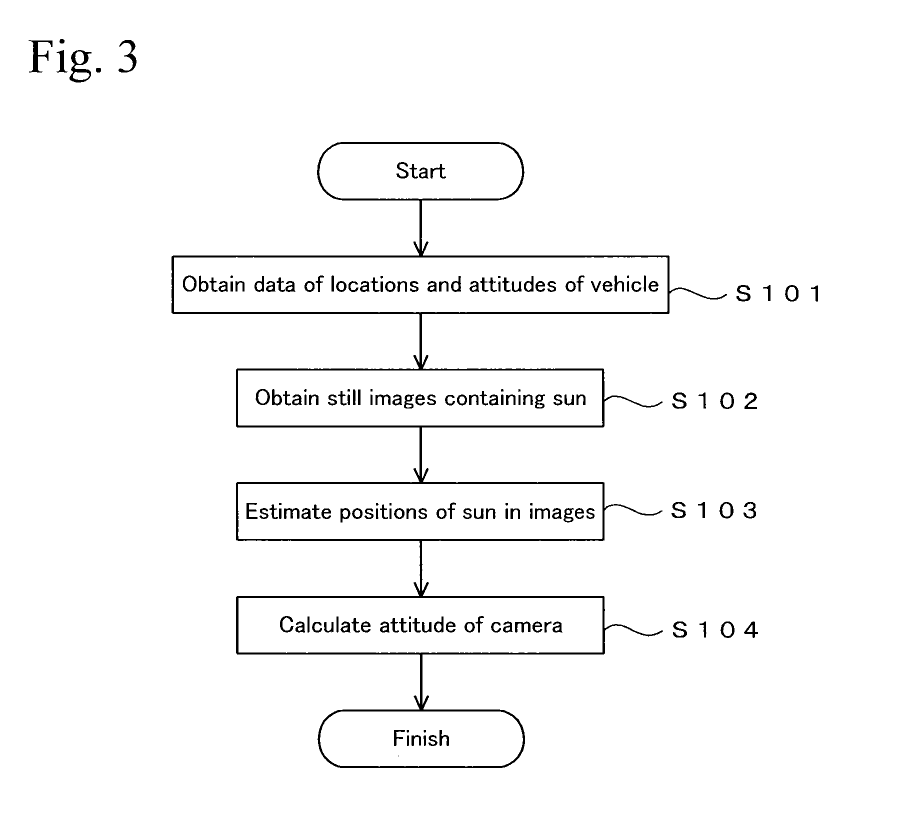
[0030]FIG. 3 shows an example of a processing procedure that is performed by the operating device 103. Programs for executing the processing shown in FIG. 3 are stored in a memory in the operating device 103 or an appropriate storage medium and are executed by the operating device 103. First, information of location and attitude of the vehicle 100 at a time “t” is obtained (step S101). The processing of this step is performed by the data obtaining unit 111. The value of the location of the vehicle 100 is obtained by the calculation that is performed by the vehicle location calculating unit 112, and the value of the attitude of the vehicle 100 is obtained from the IMU 102. Moreover, data of still images that are photographed by the camera 104 at time “t” is obtained (step S102). Here, an image containing the sun is selected as a target still image. In addition, since sunlight is extremely bright, appropriate filtering is performed, and the lightness of the target still image is adjus...


PUM


Abstract

A technique is disclosed for easily performing calibration of a camera by using a MMS. A calibration device for a camera that is configured to photograph the sun includes an in-image sun position identifying unit 115, a sun position estimating unit 113, and a camera attitude calculating unit 116. The in-image sun position identifying unit 115 identifies a position of the sun in an image that is photographed by the camera. The sun position estimating unit 113 estimates a position of the sun in the image based on orbital information of the sun. The camera attitude calculating unit 116 calculates attitude of the camera based on differences between identified positions and the estimated positions of the sun in the images.

Description

BACKGROUND OF THE INVENTION[0001]Technical Field[0002]The present invention relates to a technique for calibrating a camera.[0003]Background Art[0004]An MMS (mobile mapping system) is publicly known. In the MMS, a vehicle is equipped with a GNSS unit, a camera, a laser scanner, an IMU (Inertial Navigation Unit), etc., and the vehicle obtains three-dimensional data and images of the surroundings while travelling, whereby a three-dimensional data of the travelling environment is obtained. The three-dimensional data that is obtained by the MMS may be used for city planning, civil engineering work, disaster prevention plans, etc., for example.[0005]In the MMS, the precision of exterior orientation parameters (position and attitude) of the camera relative to the vehicle is important. The work for obtaining the exterior orientation parameters of the camera relative to the vehicle is called “calibration”. If a camera is initially fixed on a vehicle, the calibration can be performed when th...

Claims


Application Information

Patent Timeline
IPC IPC(8): G06T7/00G06T7/20
CPCG06T7/0018G06T7/004G06T2207/30252G06T2207/20224G06T2207/30244G06T7/20G06T2207/30192G06T7/80G06T7/73
Inventor SASAKI, YOUITO, TADAYUKI
Owner KK TOPCON
Learn More