
Distributed data center architecture

a data center and distributed technology, applied in data switching networks, multiplex communication, star/tree networks, etc., can solve the problems of imposing scalability challenges, high cost and complexity, and large volume of traffic up and down the switching hierarchy

Inactive Publication Date: 2016-12-29
CIENA
View PDF19 Cites 181 Cited by
  • Summary
  • Abstract
  • Description
  • Claims
  • Application Information

AI Technical Summary

Benefits of technology

The patent describes a network element that provides a single distributed data center architecture between two geographically diverse locations using a unified label structure. The network element includes a plurality of ports and a packet switch for performing Multiprotocol Label Switching (MPLS) per Hierarchical Software Defined Networking (HSDN) using the ordered label structure. The network element can use Segment Routing in the WAN and can create a Wavelength Division Multiplexing (WDM) signal for the second port over the WAN. The network element can utilize a rigid switch hierarchy or an unmatched switch hierarchy between the data center underlay and the WAN underlay. The technical effect of the patent is to provide a more efficient and reliable data center architecture that reduces latency and improves reliability between data centers.

Problems solved by technology

This imposes scalability challenges when the data center facility has maximized its space and power footprint.
A Data Center Interconnect (DCI) network is typically built as an IP routed network, with associated high cost and complexity.
This creates a large volume of traffic up and down the switching hierarchy, imposing scaling concerns.
These new data centers are typically smaller than those located in remote areas, due to limitations such as the availability of space and power within city limits.
As these smaller facilities fill up, many additional users are unable to co-locate to take advantage of the exchange services.
Today's centralized computer resources are not able to support many of the anticipated mobile application requirements without placing computer functions closer to the user.

Method used


Image

  • Distributed data center architecture
  • Distributed data center architecture
  • Distributed data center architecture

Examples


Embodiment Construction

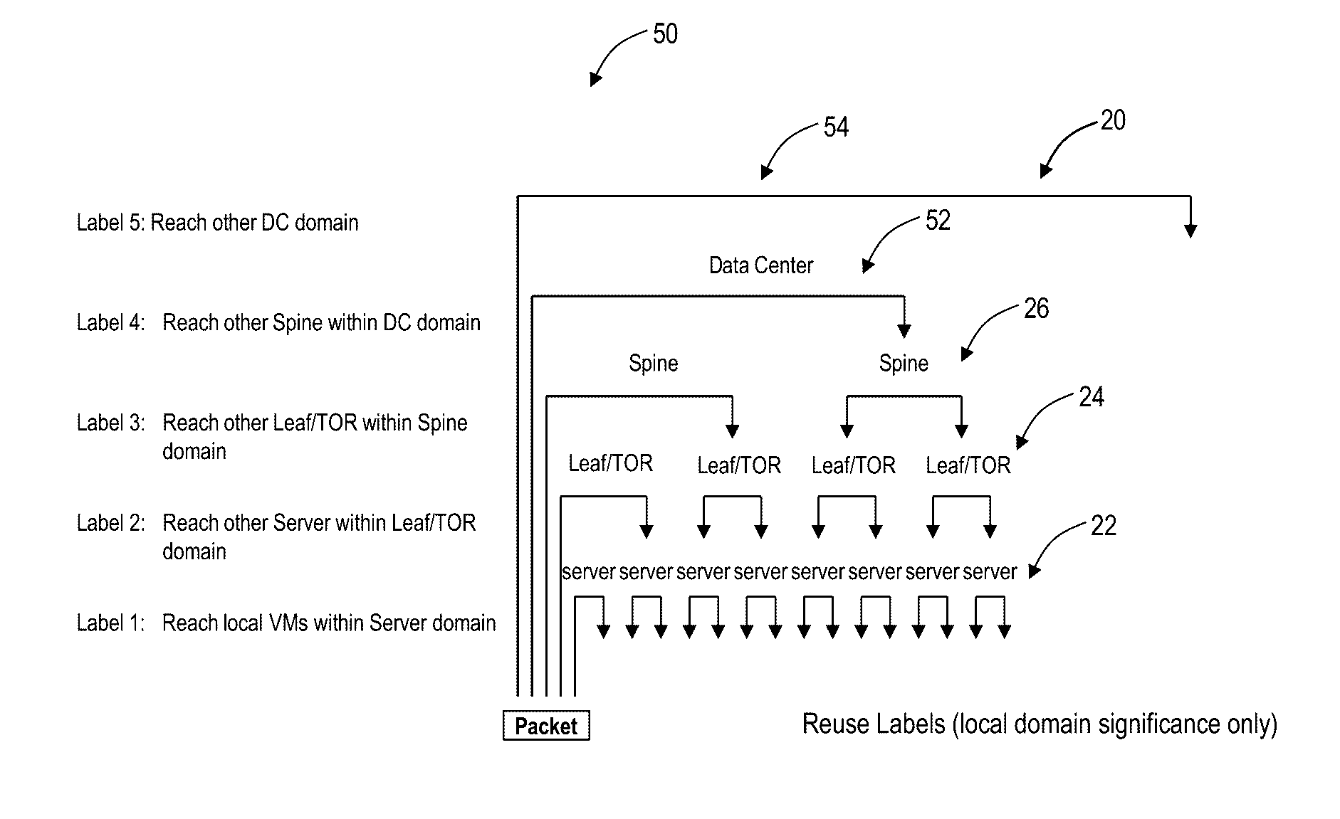
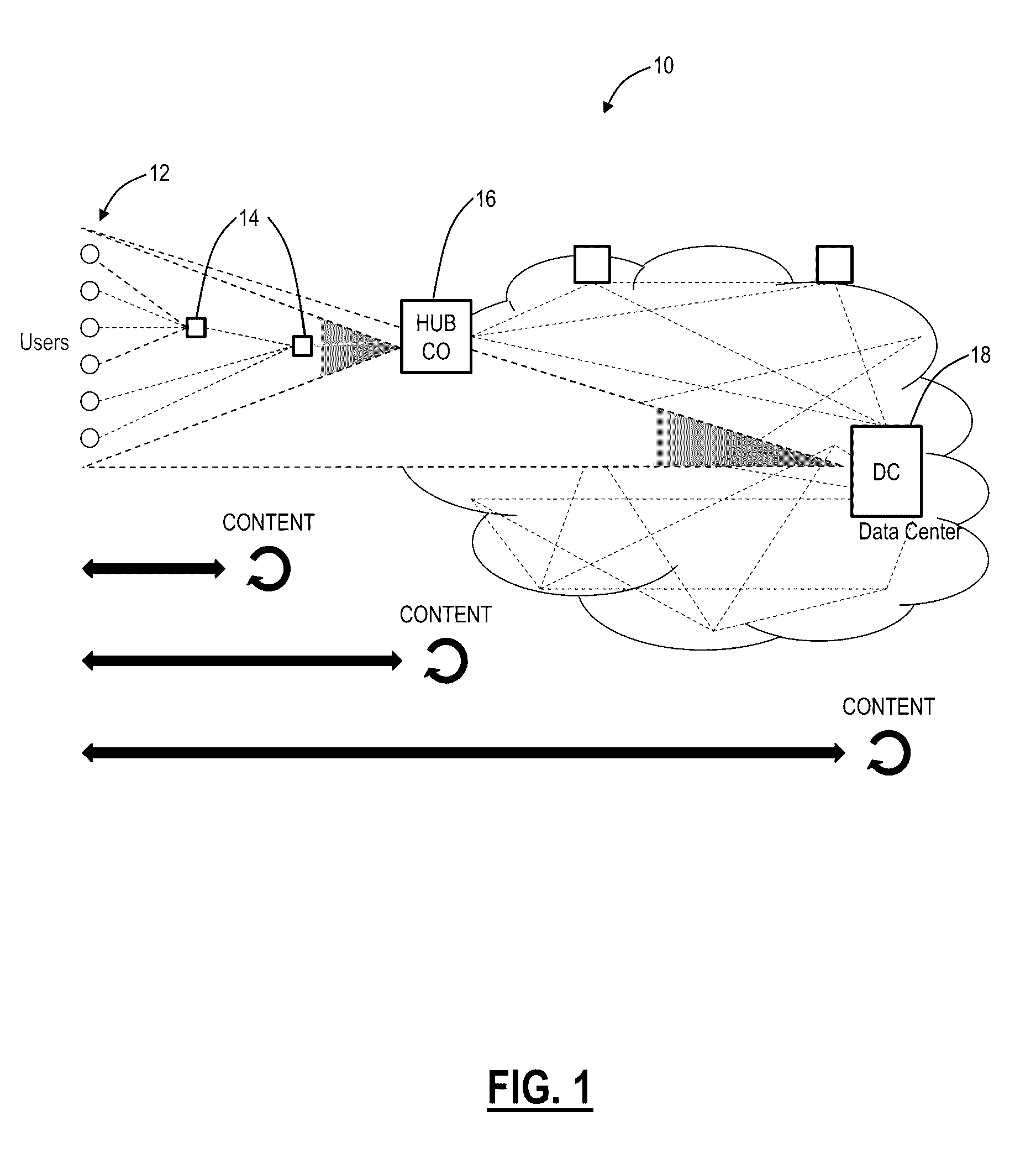
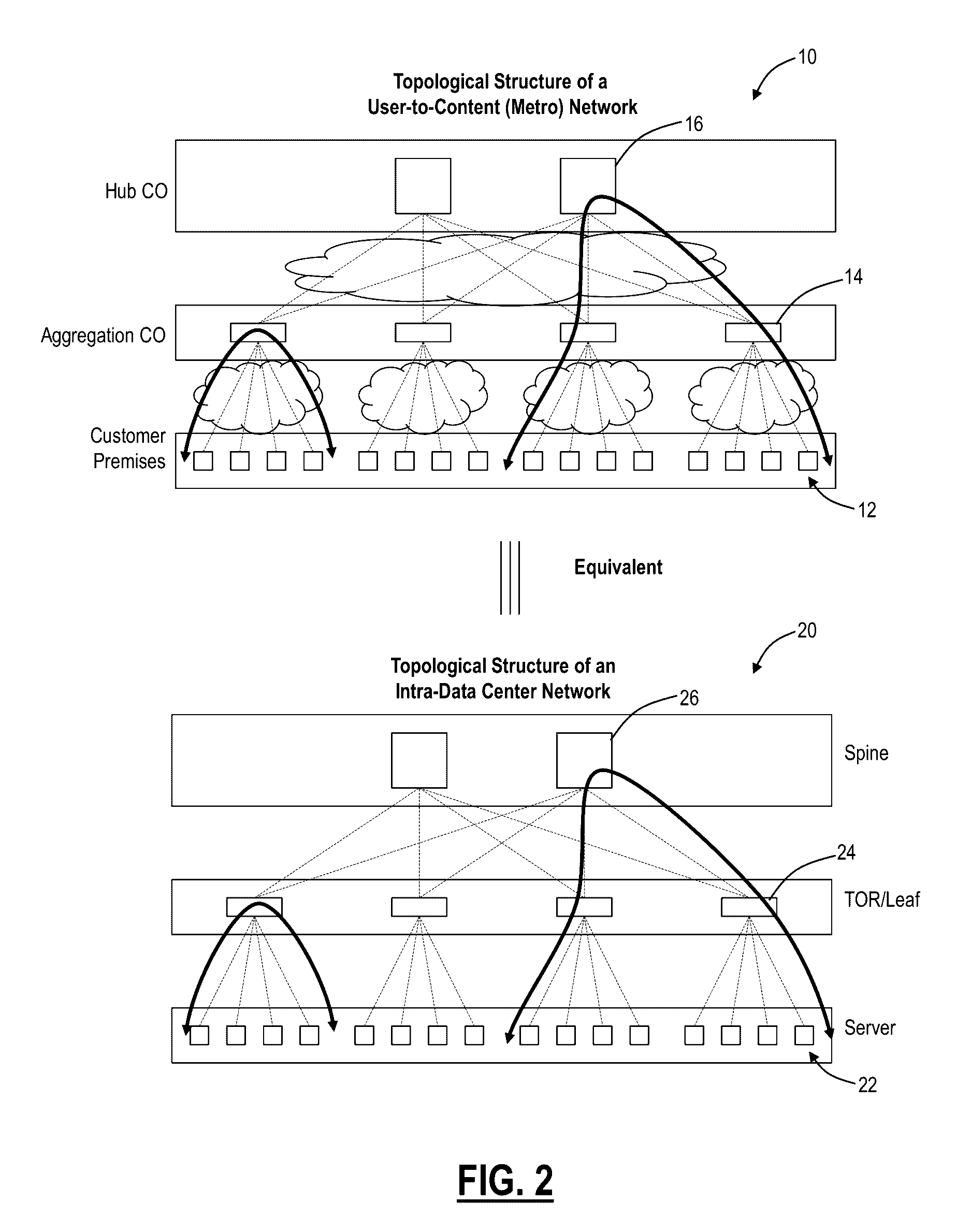
[0038]In various exemplary embodiments, systems and methods are described for a distributed data center architecture. Specifically, the systems and methods describe a distributed connection and computer platform with integrated data center (DC) and WAN network connectivity. The systems and methods enable a data center underlay interconnection of users and / or geographically distributed computer servers / Virtual Machines (VMs) or any other unit of computing, where servers / VMs are located (i) in data centers and / or (ii) network elements at (a) user sites and / or (b) in the WAN. All servers / VMs participate within the same geographically distributed data center fabric. Note, as described herein, servers / VMs are referenced as computing units in the distributed data center architecture, but those of ordinary skill in the art will recognize the present disclosure contemplates any type of resource in the data center. The definitions of underlay and overlay networks are described in IETF RFC736...


PUM


Abstract

A network element is configured to provide a distributed data center architecture between at least two data center locations. The network element includes a plurality of ports configured to switch packets between one another; wherein a first port of the plurality of ports is connected to an intra-data center network of a first data center location and a second port of the plurality of ports is connected to a second data center location that is remote from the first data center location over a Wide Area Network (WAN), and wherein the intra-data center network of the first data center location, the WAN, and an intra-data center network of the second data center location utilize an ordered label structure between one another to form the distributed data center architecture.

Description

FIELD OF THE DISCLOSURE[0001]The present disclosure generally relates to networking systems and methods. More particularly, the present disclosure relates to systems and methods for a distributed data center architecture.BACKGROUND OF THE DISCLOSURE[0002]The integration of Wide Area Networks (WANs) and data center networks is an evolving trend for network operators who have traditional network resources, Network Functions Virtualization Infrastructure (NFVI), and / or new data center facilities. Conventional intra-data center network connectivity predominantly uses packet switching devices (such as Ethernet switches and Internet Protocol (IP) routers) in a distributed arrangement (e.g., using a fat tree or leaf / spine topology based on a folded Clos switch architecture) to provide a modular, scalable, and statistically non-blocking switching fabric that acts as an underlay network for overlaid Ethernet networking domains. Interconnection between Virtual Machines (VMs) is typically base...

Claims


Application Information

Patent Timeline
IPC IPC(8): H04L12/723H04Q11/00H04J14/02H04L29/08H04L45/50
CPCH04L45/50H04L67/10H04Q2011/0077H04J14/0212H04Q2011/0016H04Q11/0066H04L45/64H04L12/44H04L12/46H04J14/0278
Inventor BLAIR, LOUDON T.BERTHOLD, JOSEPHBRAGG, NIGEL L.RANGANATHAN, RAGHURAMAN
Owner CIENA
Learn More