Eureka AIR delivers breakthrough ideas for toughest innovation challenges, trusted by R&D personnel around the world.

Optical device and luminaire

Active Publication Date: 2017-01-05
SIGNFY HLDG BV
View PDF13 Cites 2 Cited by
  • Summary
  • Abstract
  • Description
  • Claims
  • Application Information

AI Technical Summary

Benefits of technology

The invention aims to create an optical device that can create a weaving lighting effect using a single device only. It uses plural lenses with curved regions that intersect in a way to create a weaving effect. The lenses can be mounted on a carrier, and some can even be rotated to change the direction of the light. The device can be used in a luminaire with solid state lighting elements which are mounted in the lenses and can produce different colors to enhance the aesthetic appeal of the weaving light pattern. The technical effects of the invention include a more efficient and aesthetically pleasing weaving lighting effect.

Problems solved by technology

One of the technical challenges associated with projecting light effects onto an object area such as an object surface is that it is not straightforward to create the desired light effect.
A drawback of such a device is that the gobo's block part of the emitted light to create the desired patterns, which therefore negatively affects to luminous efficiency of the device.
However, this architectural mesh is relatively costly to manufacture and furthermore the integration of optical elements in the light element may be cumbersome as the light element should have a small form factor to be integrated in the architectural mesh in an unobtrusive manner, which limits the type of lighting effects that can be generated with the mesh.

Method used


Image

  • Optical device and luminaire
  • Optical device and luminaire
  • Optical device and luminaire

Examples


Embodiment Construction

[0031]It should be understood that the Figures are merely schematic and are not drawn to scale. It should also be understood that the same reference numerals are used throughout the Figures to indicate the same or similar parts.

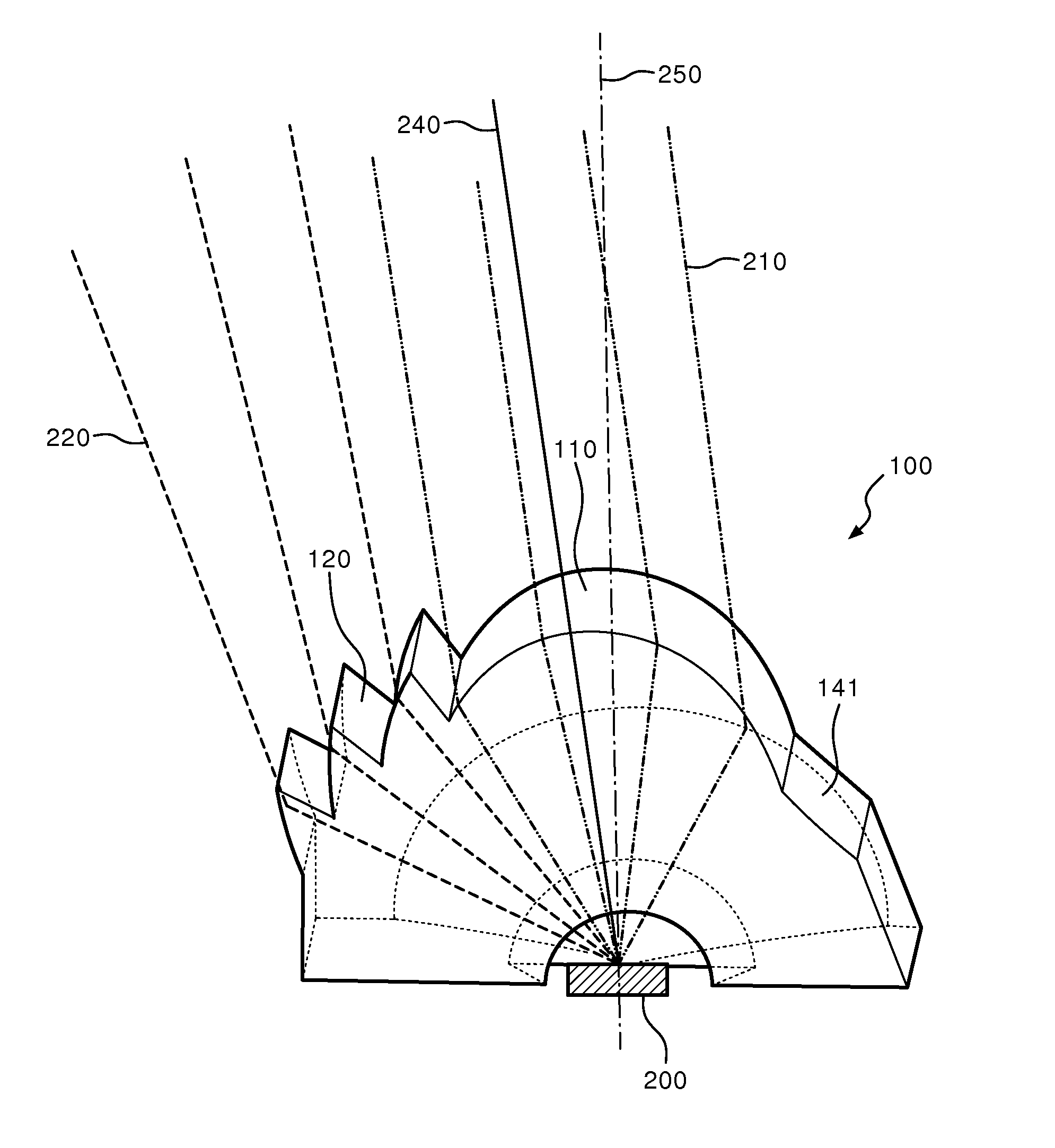
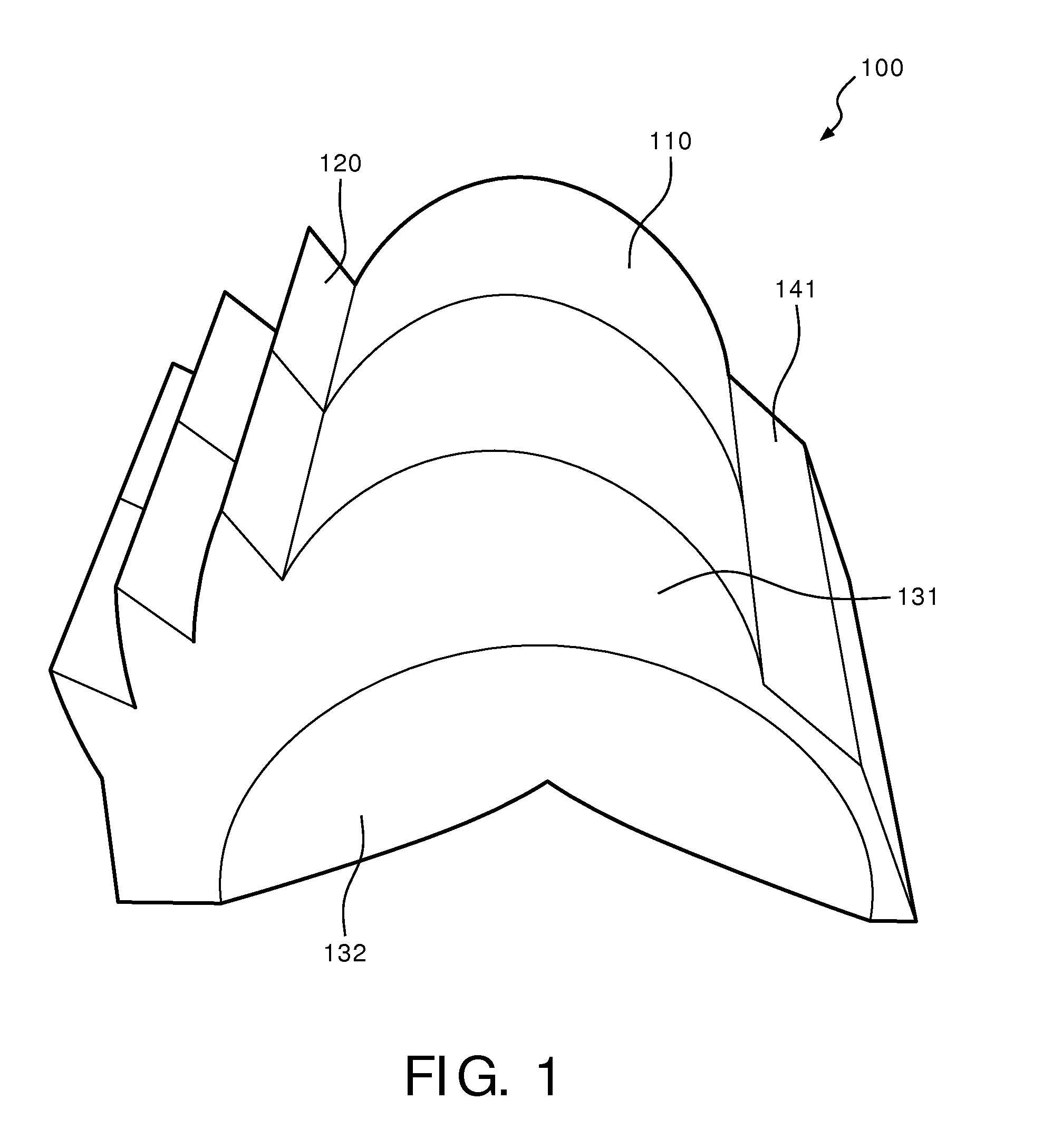
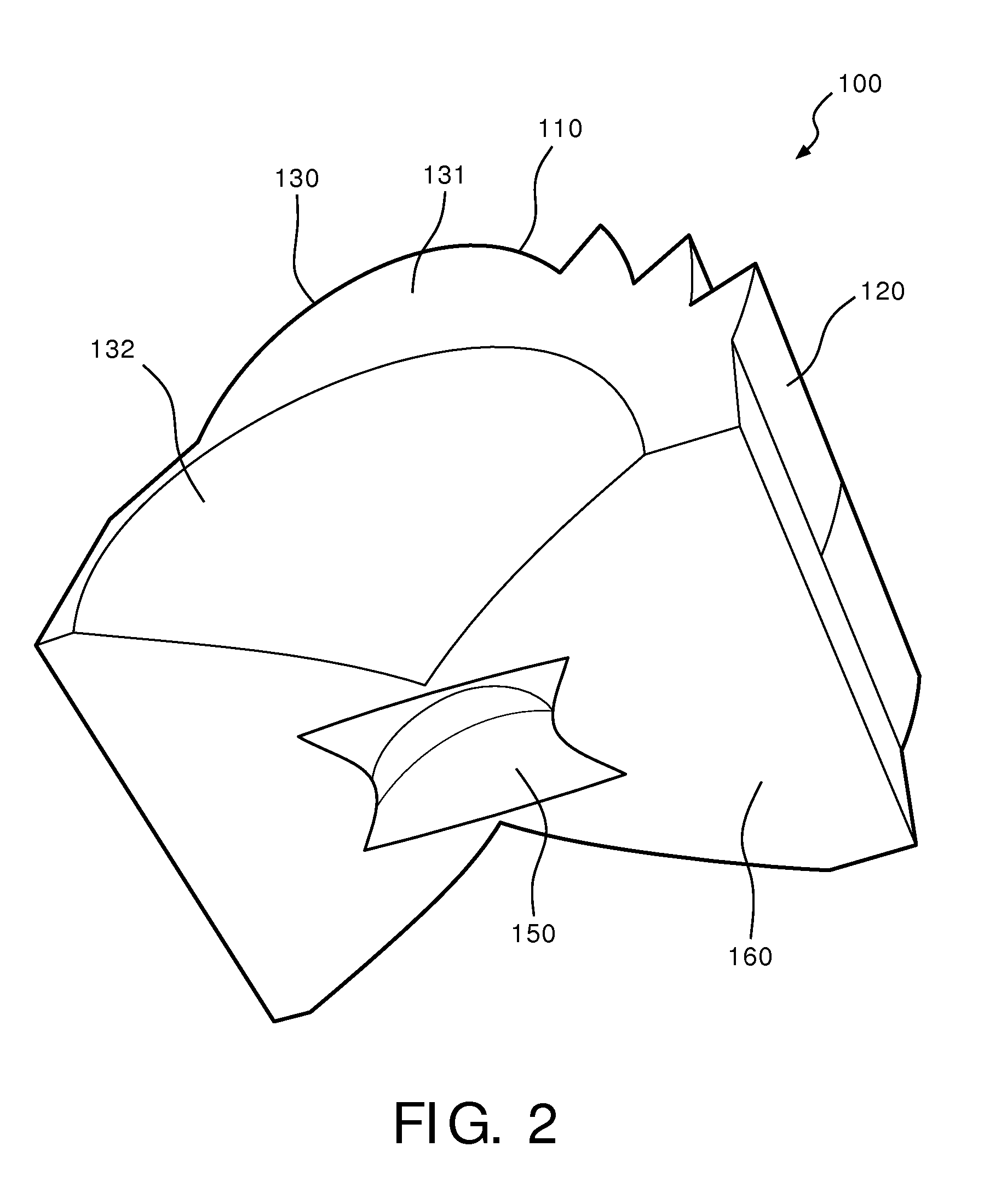
[0032]FIG. 1-4 schematically depict various views of a lens 100 for an optical device according to an embodiment. The lens 100 typically comprises a cavity 150 for housing a solid state lighting (SSL) element 200 such as a light emitting diode (LED). Any suitable type of LED may be used for this purpose. The cavity 150 may have an inner surface comprising two opposing flat side surfaces 152 adjoined by a refractive curved surface 154, e.g. a convex surface, which is shaped to collimate at least a central portion of the light distribution produced by the LED 200, e.g. light emitted under an angle ranging from 0° to 30° relative to the optical axis of the SSL element 200, although other ranges are equally feasible. The inner surface of the cavity 150 or at leas...


PUM


Abstract

Disclosed is an optical device (10) comprising a plurality of lenses (100) for projecting a plurality of parallel beams (202, 204) having a predetermined width towards an object area, wherein each lens comprises a lens body including a cavity (150) for housing a solid state lighting element (200); a pair of opposing internally reflecting side surfaces (130) for constraining said beam within said predetermined width; and a light exit surface delimited by said opposing side surfaces, the light exit surface comprising a curved region (110) extending from a first further side surface (141) extending between the opposing side surfaces and shaped to generate a collimated beam portion along an optical axis; and a stepped region in between the curved region and a second further side surface (142) extending between the reflecting side surfaces, wherein said steps are defined by a plurality of prismatic protrusions (120), each of said protrusions laterally extending between said opposing side surfaces. A luminaire including at least one such an optical device is also disclosed.

Description

FIELD OF THE INVENTION[0001]The present invention relates to an optical device for creating a weaving lighting effect.[0002]The present invention further relates to a luminaire comprising at least one such an optical device.BACKGROUND OF THE INVENTION[0003]Architectural aesthetics is an important and popular industry. Nowadays, people tend to integrate lighting technology into architectural designs to create artistic lighting effects for aesthetic purposes.[0004]One of the technical challenges associated with projecting light effects onto an object area such as an object surface is that it is not straightforward to create the desired light effect. An example of a light pattern-generating lighting device is provided in US2014 / 192080 A1, which discloses a lighting device including so-called gobo's to generate desired patterns. A drawback of such a device is that the gobo's block part of the emitted light to create the desired patterns, which therefore negatively affects to luminous ef...

Claims


Application Information

Patent Timeline
IPC IPC(8): F21V5/00F21V7/09F21V5/02
CPCF21S10/00F21V5/007F21V5/02F21V5/045F21V5/08F21V7/0091F21V14/06F21V17/02F21W2121/00F21W2121/004F21Y2113/10F21Y2115/10G02B19/0028F21V7/09
Inventor YANG, XIUYAN, CAIJIESONG, GANGWANG, WEI
Owner SIGNFY HLDG BV
Why Eureka
Eureka Blog
Learn More