Geolocating a remote emitter

a technology of remote emitter and geolocation, which is applied in the direction of measurement devices, communication jamming, instruments, etc., can solve the problems of long observation time and inaccurateness, and achieve the effect of reducing receiver noise, reducing the impact of random receiver noise, and increasing observation tim

Active Publication Date: 2017-01-05
RAYTHEON CO
View PDF6 Cites 28 Cited by
  • Summary
  • Abstract
  • Description
  • Claims
  • Application Information

AI Technical Summary

Benefits of technology

[0005]Embodiments of the present disclosure use special signal processing to overcome the significant measurement problem of achieving accurate measurements with noisy data and platform flexure and vibration. Accuracy of both measured and predicted TDOA and FDOA typically is enhanced by combining values from observation of several pulse observations, and by calculating individual values by analysis of several pulses of the emitter waveform. Increasing the observation time reduces the

Problems solved by technology

However, long observations become inaccurate when platform vibration

Method used


Image

  • Geolocating a remote emitter
  • Geolocating a remote emitter
  • Geolocating a remote emitter

Examples


Embodiment Construction

[0016]A description of example embodiments of the present disclosure follows.

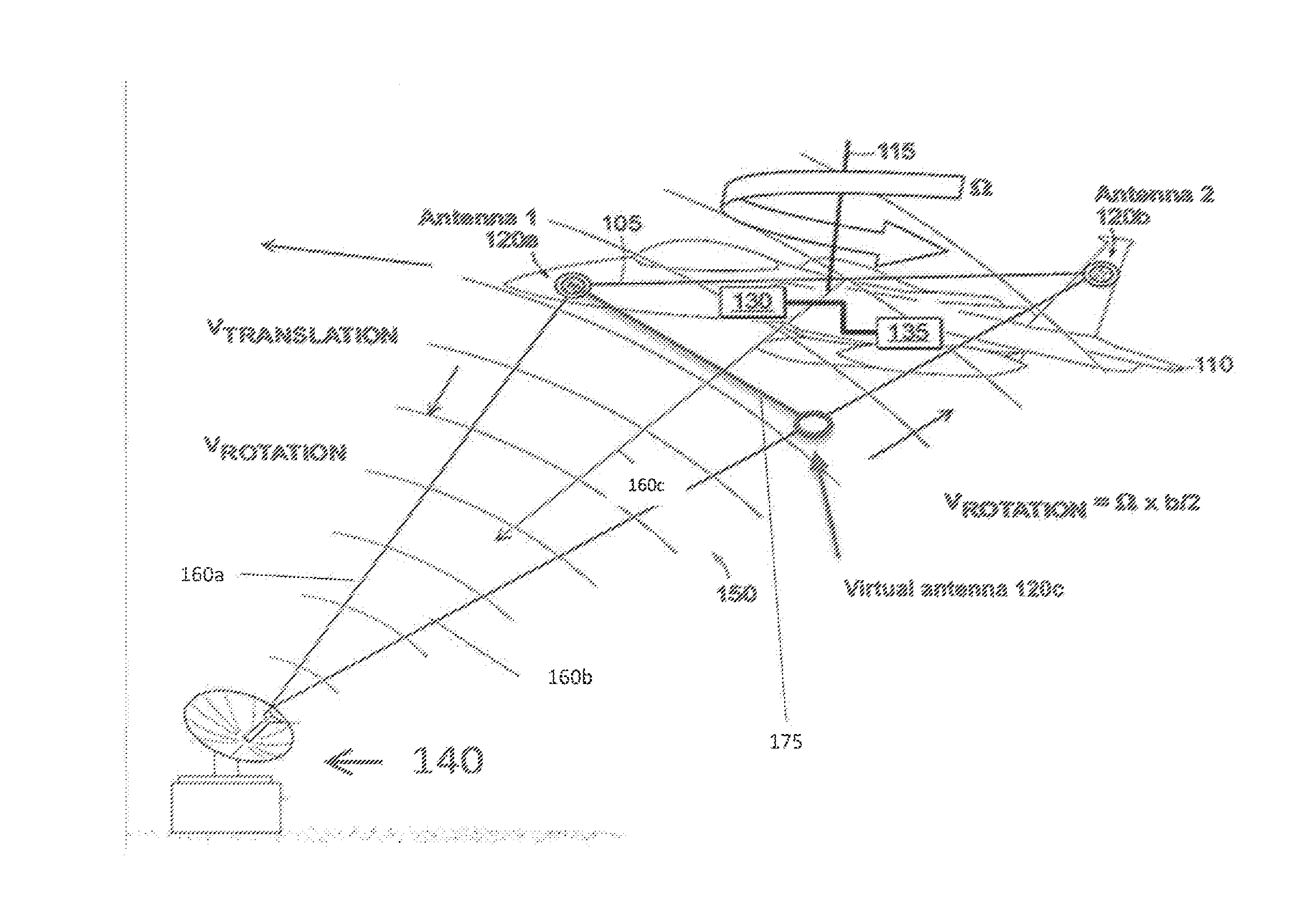
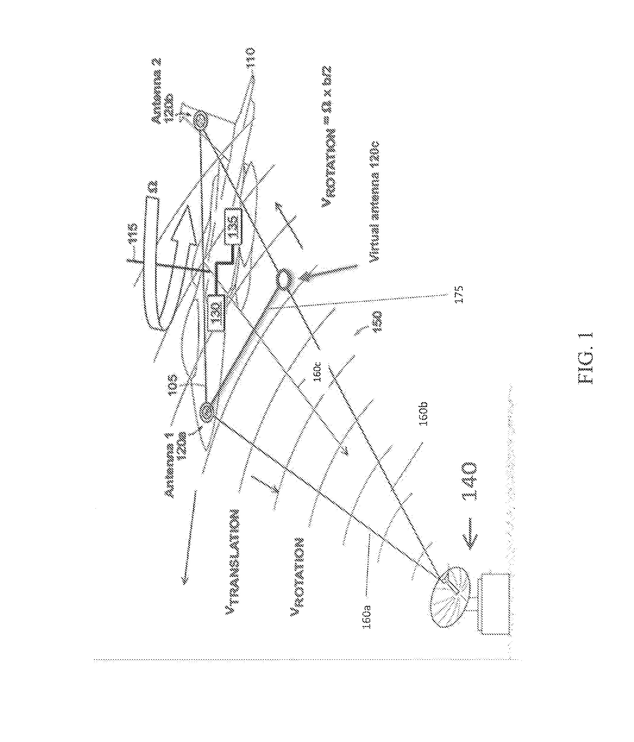
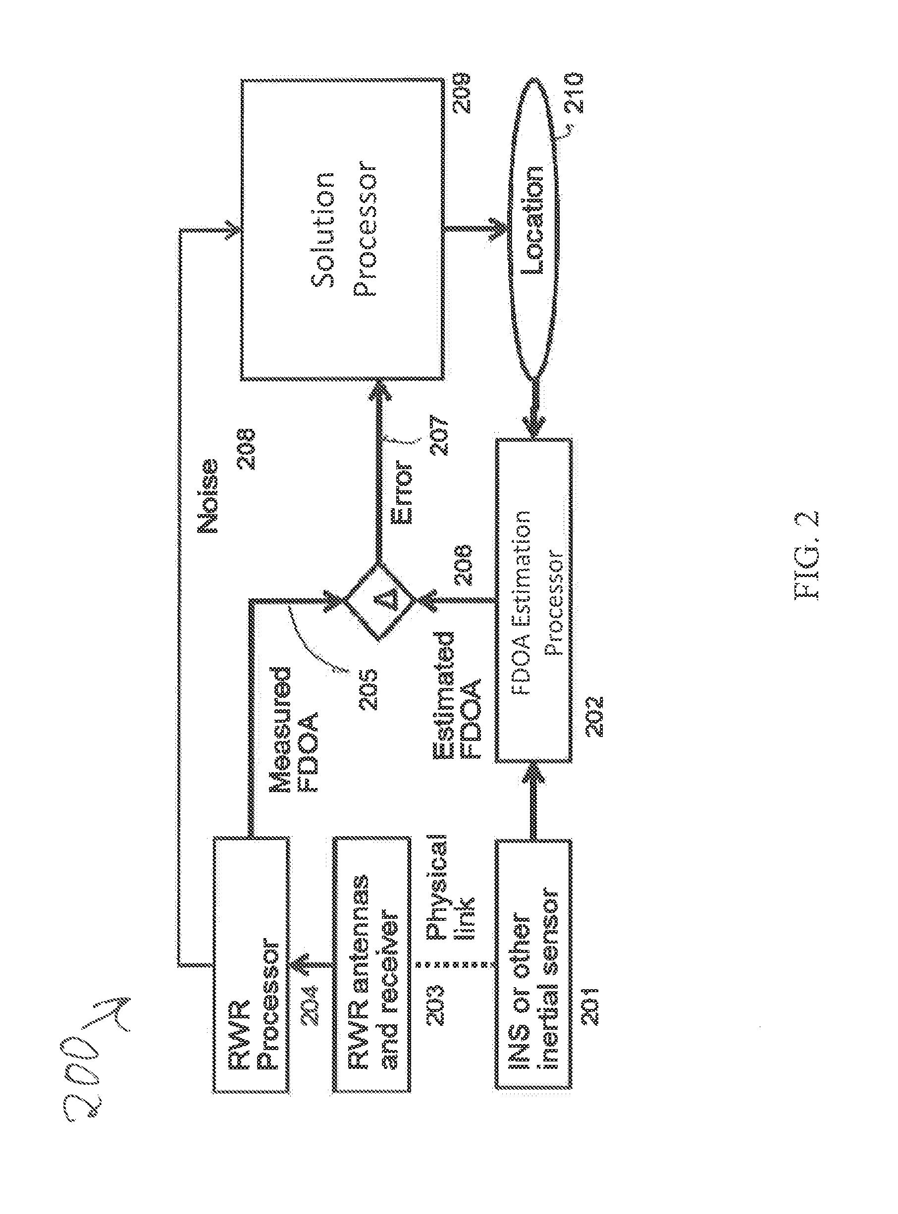
[0017]A technique for determining the location of a radar emitter is based on passive measurement of radar pulses received by two receivers separated by a fixed distance on a moving platform (e.g., an aircraft). The measured radar pulses together with measured platform motion and position, enable geometric location of the radar emitter. In the preferred embodiment, the radar measurements are made with a radar warning receiver (RWR), while the platform measurements are made with position-aided navigation system (NAV). The description to follow also applies to other embodiments, such as an acoustic or sonar system, a semi-active radar system, or an optical or ladar system.

[0018]A geolocation technique determines the location on earth of a radar emitter, using measurements of time difference of arrival (TDOA) or frequency difference of arrival (FDOA) of a pulsed waveform. Joint solutions based on TDOA and FDOA...


PUM


Abstract

A method for improving geolocation accuracy in a passive radar warning receiver, using synchronized data curve-fit and interpolation to asynchronous and noisy receiver and navigation measurements over observation periods that are extended to reduce inaccuracies caused by noise. The present disclosure yields synchronized data samples at intervals short enough that constant-rate equations are valid, even though the actual motions over the observation interval may be more complex and have higher-order dynamics. It reduces noise, synchronizes data samples, and is readily adapted to motions with variable acceleration. The method generates rate samples short enough to satisfy constant rate assumptions, yet fit data over intervals long enough to enhances measurement accuracy by reducing measurement noise.

Description

GOVERNMENT SUPPORT[0001]This invention was conceived with government support under N68936-05-D-0033 awarded by the Naval Air Warfare Center Weapons Division. The government has certain rights in the present disclosure.FIELD OF THE INVENTION[0002]The present invention generally relates to geo-location of remote emitters devices, and in particular to mobile radar warning receivers with this function.BACKGROUND[0003]There is a need for airborne radar warning receivers (RWR)s to determine the specific location of a radar emitter through detection and analysis of radar signals emitted by the radar emitter, combined with measurements of RWR position and motion measured by a aircraft navigation system (NAV) or other means. Such determination of radar emitter position in earth coordinates is commonly referred to as geolocation. Geolocation techniques typically capture samples of the radar emitter signal with passive receivers mounted on a moving platform, such as an aircraft, and calculate ...

Claims


Application Information

Patent Timeline
IPC IPC(8): G01S5/06G01S5/02
CPCG01S7/021H04K3/22H04K3/45H04K3/68H04K3/82H04K3/822G01S5/06G01S5/0249G01S5/0246G01S5/0221G01S2205/03G01S5/0278
Inventor WELLMAN, WILLIAM H.SAVAGE, LEE M.BROAD, JOHN T.
Owner RAYTHEON CO
Why Eureka
Try Eureka