Cable termination

a cable termination and cable technology, applied in the direction of cable terminations, coupling device connections, instruments, etc., can solve the problems of requiring specialized chemicals, molds and other equipment, cleaning, controlled laboratory environment, mold delamination, etc., to eliminate potential leak paths and other failure modes inherent in the termination, the effect of simple termination architectur

Active Publication Date: 2017-01-05
PONTUS SUBSEA CONNECTORS LLC
View PDF3 Cites 11 Cited by
  • Summary
  • Abstract
  • Description
  • Claims
  • Application Information

AI Technical Summary

Benefits of technology

[0012]In the invented termination the cable is mechanically attached to the connector by way of a grip in the rear portion of an elongated shell, which shell, in turn, is mechanically attached on its forward end to a connector body. The shell forms a protective barrier for the more vulnerable portions of the termination contained within it. A flexible-walled fluid-filled chamber encloses the union between a cable's electrical and / or optical fiber conductive elements and the respective conductive elements of the connector. The chamber's flexible walled enclosure is exposed to the in-situ environment, allowing the fluid pressure within the chamber to change with changing outside pressure, and to volumetrically expand or contract due to temperature and pressure changes. A cable-end breakout boot seal is integrally formed as part of the flexible-walled chamber enclosure, thereby greatly simplifying the architecture of the termination. The breakout boot seal is kept in place by a positive mechanism that retains it on the cable's end. The unified chamber enclosure and breakout boot seal structure includes a pressure relief feature that vents cable internal overpressure to the outside environment. The device is quickly and easily installable, and if necessary, removable and reparable in the field with no special training or tools. At the same time, the integrated chamber enclosure and breakout boot seal eliminate some of the potential leak paths and other failure modes inherent in more complex prior-art terminations. The economy and ease of installation, without need of laboratory conditions, should favor the use of the invention over traditional over-molded terminations in a wide variety of applications.

Problems solved by technology

Over-molded terminations have the disadvantages that they must be made in a clean, controlled laboratory environment and require specialized chemicals, molds and other equipment.
Under some conditions molded terminations also suffer from de-lamination of the bonds that bind and seal them to the other components.
This type of termination is field installable and repairable without specialized equipment; however, its use is restricted to very light-duty operations because there are no provisions to keep cable torque, bending, compression, or tension from working directly on the conductor junctions.
Pressure compensating the terminations relieves much of the stress on the conductor junctions, and reduces the possibility of environmental fluid intruding into the termination.
Such oil loss can quickly lead to chamber collapse and catastrophic termination failure.
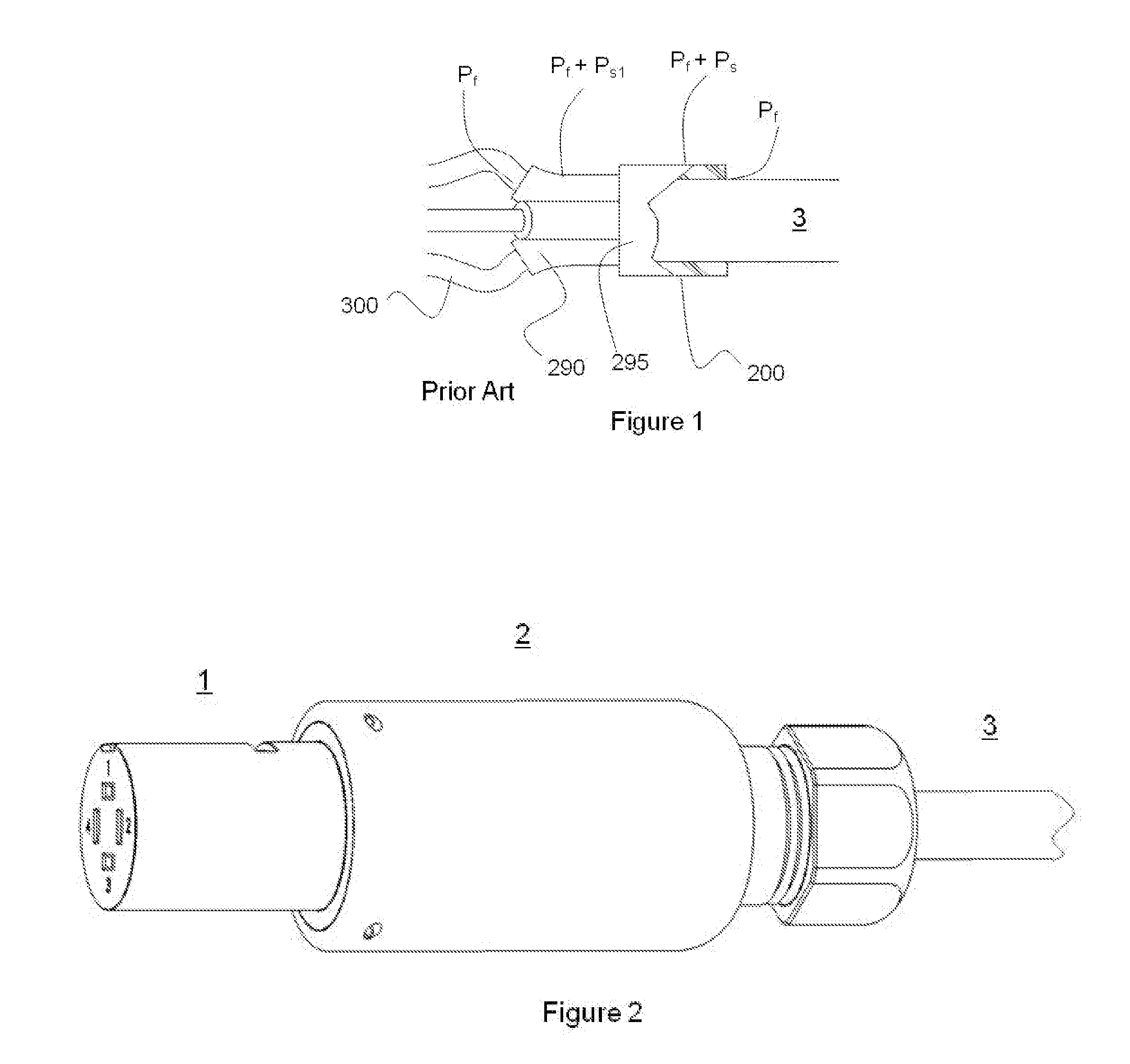
As discussed in U.S. Pat. No. 6,796,821, prior art elastomeric breakout boot seals are easily displaced from their sealing positions, particularly in applications wherein there is rough handling or an overpressure of mobile material within the cable itself that might extrude into the boot seal and push it out of sealing engagement or even completely off of the cable's end.

Method used


Image

  • Cable termination
  • Cable termination
  • Cable termination

Examples


first embodiment

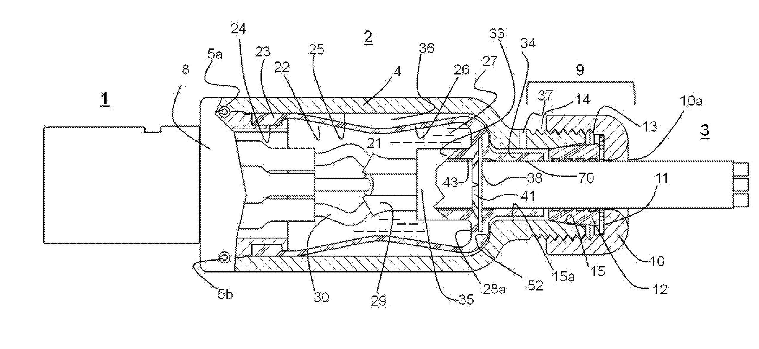
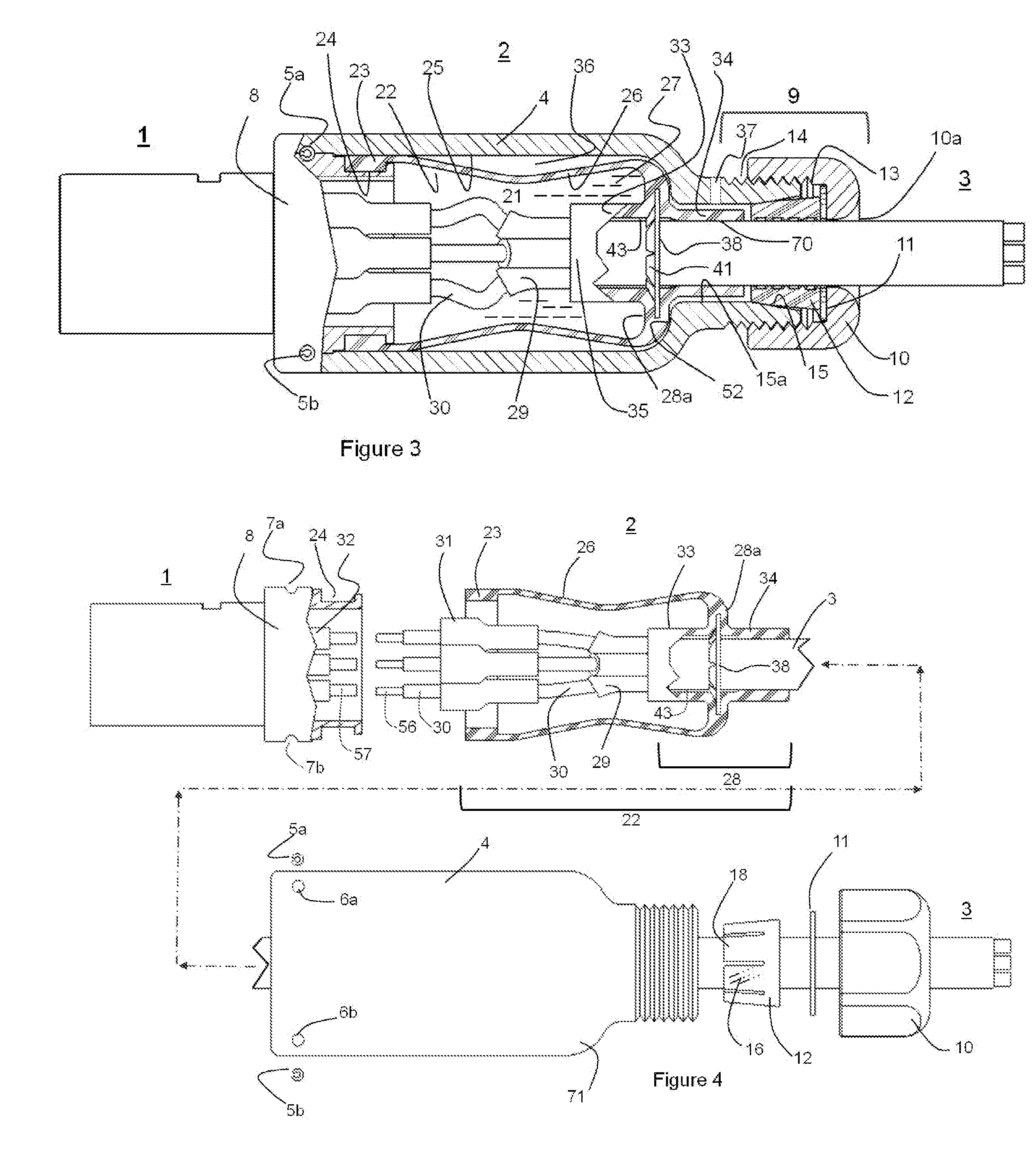
[0032]FIG. 2 is an overall oblique view of invented termination 2 used to join connector 1 to cable 3, and FIG. 3 is a partially sectioned view of the assembly shown in FIG. 2. FIG. 4 is a partially sectioned exploded view of the assembly shown in FIG. 2.

[0033]Looking now at FIGS. 3 and 4, underwater connector 1 is mechanically joined to the forward end of termination shell 4 by spring pins 5a and 5b. Pins 5a and 5b seat in respective through holes 6a and 6b in termination shell 4, and in respective slots 7a and 7b in connector back shell 8, thereby both rotationally and axially locking termination shell 4 to connector 1. Cable 3 passes into the rearward portion of termination shell 4 through cable grip assembly 9. Connector 1, shell 4, and grip assembly 9 altogether form the termination's protective housing. Shell 4 may be made of any substantially rigid material such as hard plastic or metal that is suitably rugged for the intended application.

[0034]Cable grip assembly 9 comprises...

second embodiment

[0053]There are alternate ways that would be useful in some circumstances to retain chamber enclosure 22 including boot seal portion 28 in position relative to cable 3 within the termination assembly. As an example of such circumstances, the cable to be terminated might have an outer jacket that's too soft to be adequately held in place by a push-nut type fastener such as that just described. An alternate termination construction is shown in FIGS. 9-12 and 14. In this alternate embodiment plain washer 80 replaces retainer 38 of the earlier embodiment. Washer 80 is sized with an inner diameter slightly larger than the outer diameter of cable 3, and an outer diameter somewhat larger than inner diameter 15 of shell 4. Standoff 83 (FIG. 10) has a disc-shaped end 84 with through-hole 85 and standoff rods 86. Through-hole 85 is sized just slightly larger than the outer diameter of sleeve 33 of chamber enclosure 22. Standoff rods 86 are inserted into sockets (not shown) in the rear wall of...


PUM


Abstract

The cable termination may include a housing and a cable having at least one conductor disposed within the housing with an elastomeric body disposed in the housing and constrictively stretched over a portion of the cable. A retainer may be disposed around a portion of the cable for retaining the elastomeric body on the cable. The cable termination may also include an enclosure capable of changing volumetrically in response to fluctuating pressure disposed in the housing and around a portion of the cable.

Description

CROSS-REFERENCE TO RELATED APPLICATION[0001]This application claims the benefit under 35 U.S.C. §119(e) of the earlier filing date of U.S. Provisional Patent Application No. 62 / 186,605 filed on Jun. 30, 2015, the disclosure of which is incorporated by reference herein.FIELD OF THE INVENTION[0002]Embodiments of this invention relate generally to methods and apparatus for sealably joining cables to other devices for use in harsh environments such as seawater.BACKGROUND OF THE INVENTION[0003]There are a great many harsh environment applications in which cables carrying electrical and / or fiber-optical conductors are used to network submersible devices such as pumps, motors, and environmental sensors. In these applications, the cables are usually either terminated directly to the devices, or are terminated to connectors which then connect to the devices.[0004]The term “cable termination” as used herein consists of the union between a cable's conductive elements and the respective conduct...

Claims


Application Information

Patent Timeline
Patent Type & Authority Applications(United States)
IPC IPC(8): G02B6/38H02G15/007H02G15/04
CPCG02B6/4428H01R13/5205H01R13/523H02G15/013H02G15/04G02B6/3816G02B6/3887G02B6/3865G02B6/3888
Inventor CAIRNS, JAMES L.
Owner PONTUS SUBSEA CONNECTORS LLC
Why Eureka
Try Eureka