In addition, known sensors have limited functionality directed at motion and also have limited communications capabilities.
Know sensors are specific to a sport or piece of equipment and are incapable of being utilized in multiple pieces of equipment by decoupling and recoupling with a second piece of equipment for example.
There are no known helmet based accelerometers that are retrofittable into an existing helmet for example with or without local LED displays to indicate potential
concussion level acceleration.
There are no known systems that enable a display to be sent to a monitoring parent or physician based on anything other than current
vital signs.
This technique has various limitations including inaccurate and inconsistent subjective analysis based on video for example.
Known implementations utilize a stationary multi-camera
system that is not portable and thus cannot be utilized outside of the environment where the system is installed, for example during an athletic event such as a golf tournament.
These fixed installations are extremely expensive as well.
In addition, existing solutions do not contemplate mobile use, analysis and messaging and / or comparison to or use of previously stored motion capture data from the user or other users or
data mining of large data sets of motion capture data.
To summarize, motion capture data is generally used for immediate monitoring or sports performance feedback and generally has had limited and / or primitive use in other fields.
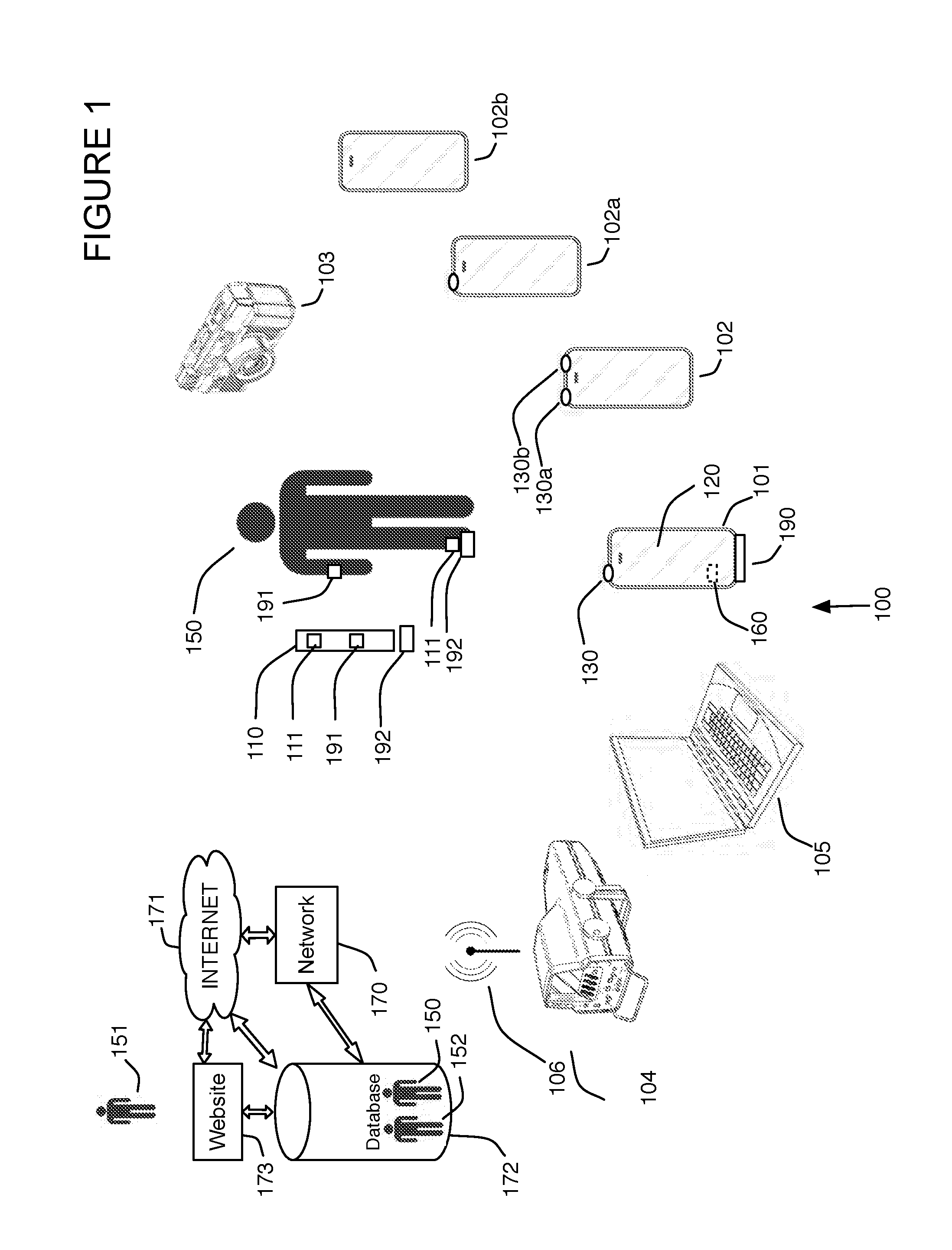
There are no known systems that allow for a group of mobile devices to share data to form three-dimensional motion capture data by
triangulation of visual markers.
There are no known systems that allow for a
mobile device without a camera to obtain images from cameras or other mobile devices with cameras to display motion capture data.
In addition, known systems do not save images of users along with motion capture data for later use, including gaming, morphological comparing, compliance, tracking calories burned, work performed, monitoring of children or elderly based on motion or previous motion patterns that vary during the day and night,
safety monitoring for troops when G-forces exceed a threshold or motion stops, local use of running,
jumping throwing motion capture data for example on a
cell phone including
virtual reality applications that make use of the user's current and / or previous data or data from other users, or play music or select a play
list based on the type of motion a user is performing or
data mining.
There are no known mobile motion captures systems that allow for a user to align a camera correctly along the horizontal before capture of motion data having horizontally aligned images.
There are no known systems that allow for motion capture elements such as
wireless sensors to seamlessly integrate or otherwise couple with a user or shoes, gloves, shirts, pants, belts, or other equipment, such as a
baseball bat, tennis racquet or
golf club for local analysis or later analysis in such a small format that the user is not aware that the sensors are located in or on these items.
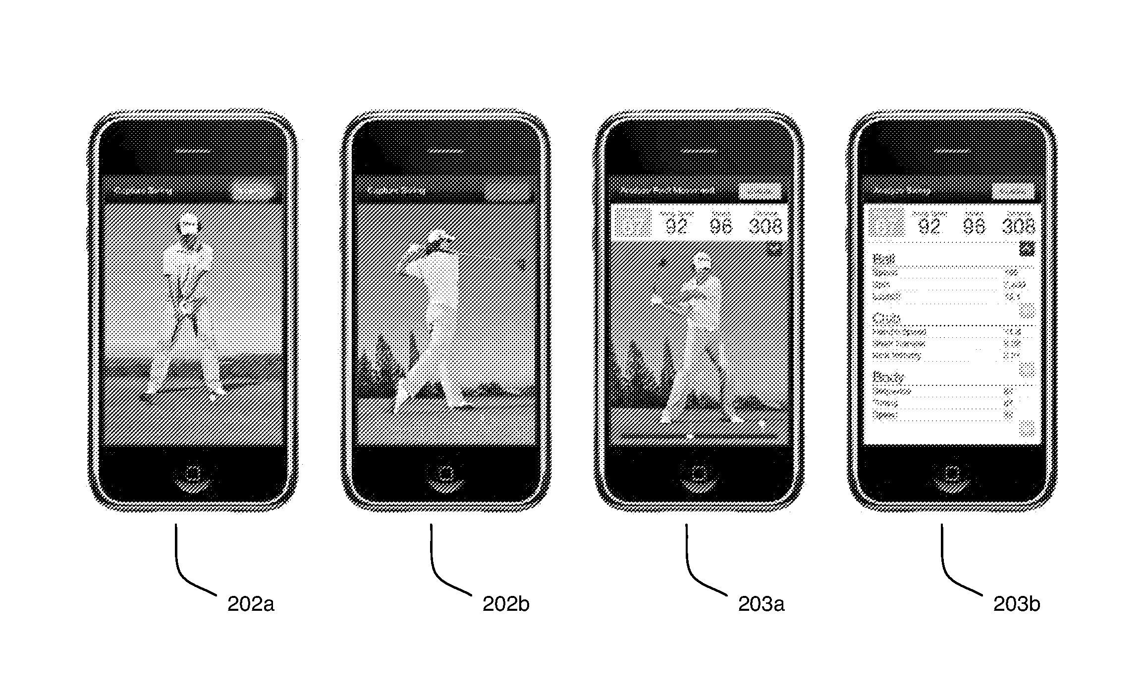
In addition, for sports that utilize a piece of equipment and a ball, there are no known portable systems that allow the user to obtain immediate
visual feedback regarding ball
flight distance, swing speed, swing efficiency of the piece of equipment or how centered an
impact of the ball is, i.e., where on piece of equipment the collision of the ball has taken place.
These systems do not allow for users to play games with the motion capture data acquired from other users, or historical players, or from their own previous performances.
Known systems do not allow for
data mining motion capture data from a large number of swings to suggest or allow the searching for better or optimal equipment to match a user's motion capture data and do not enable original equipment manufacturers (OEMs) to make business decisions, e.g., improve their products, compare their products to other manufacturers, up-sell products or contact users that may purchase different or more profitable products.
In addition, there are no known systems that utilize motion capture data mining for equipment fitting and subsequent point-of-sale
decision making for instantaneous
purchasing of equipment that fits an athlete.
Furthermore, no known systems allow for custom
order fulfillment such as assemble-to-order (ATO) for custom
order fulfillment of sporting equipment, for example equipment that is built to customer specifications based on motion capture data mining, and shipped to the customer to complete the point of sales process.
In addition, there are no known systems that use a
mobile device and RFID tags for passive compliance and monitoring applications.
For example, known systems for counting golf shots are cumbersome and require
electronics on each
golf club and / or switches that a user is required to operate.
There are no known systems that allow a golfer to easily
record a shot and location of a shot automatically and / or prompt a user to remember to
record each shot for a particular club without a battery and active
electronics on the club, for example that is not a practice shot.
Known systems do not save the shots per user per course over time in a
database and do not contemplate data mining the motion capture data, or shot count and distance data for example to allow for OEMs to purchase access to the
database for business
decision making for example.
There are no known systems that enable data mining for a large number of users related to their motion or motion of associated equipment to find patterns in the data that allows for business strategies to be determined based on heretofore undiscovered patterns related to motion.
There are no known systems that enable obtain
payment from OEMs, medical professionals, gaming companies or other end users to allow data mining of motion data.
Use of a single sensor for each quantity typically requires trading off sensor range for sensor resolution: very precise sensors generally have limited measurement ranges, and conversely sensors with wide measurement ranges typically have limited precision.
There are no known systems that combine multiple sensors for a single
physical quantity to achieve the benefits of both wide range and high precision.

