

Structured Porous Metamaterial
a metamaterial and structure technology, applied in the direction of material strength using tensile/compressive forces, additive manufacturing apparatus, additive manufacturing processes, etc., can solve the problem of little artificial metamaterials with nlc or nac availabl
- Summary
- Abstract
- Description
- Claims
- Application Information
AI Technical Summary
Benefits of technology
Problems solved by technology
Method used
Image

Examples
example 1
Cubic Base Cell with Spherical Shape Void
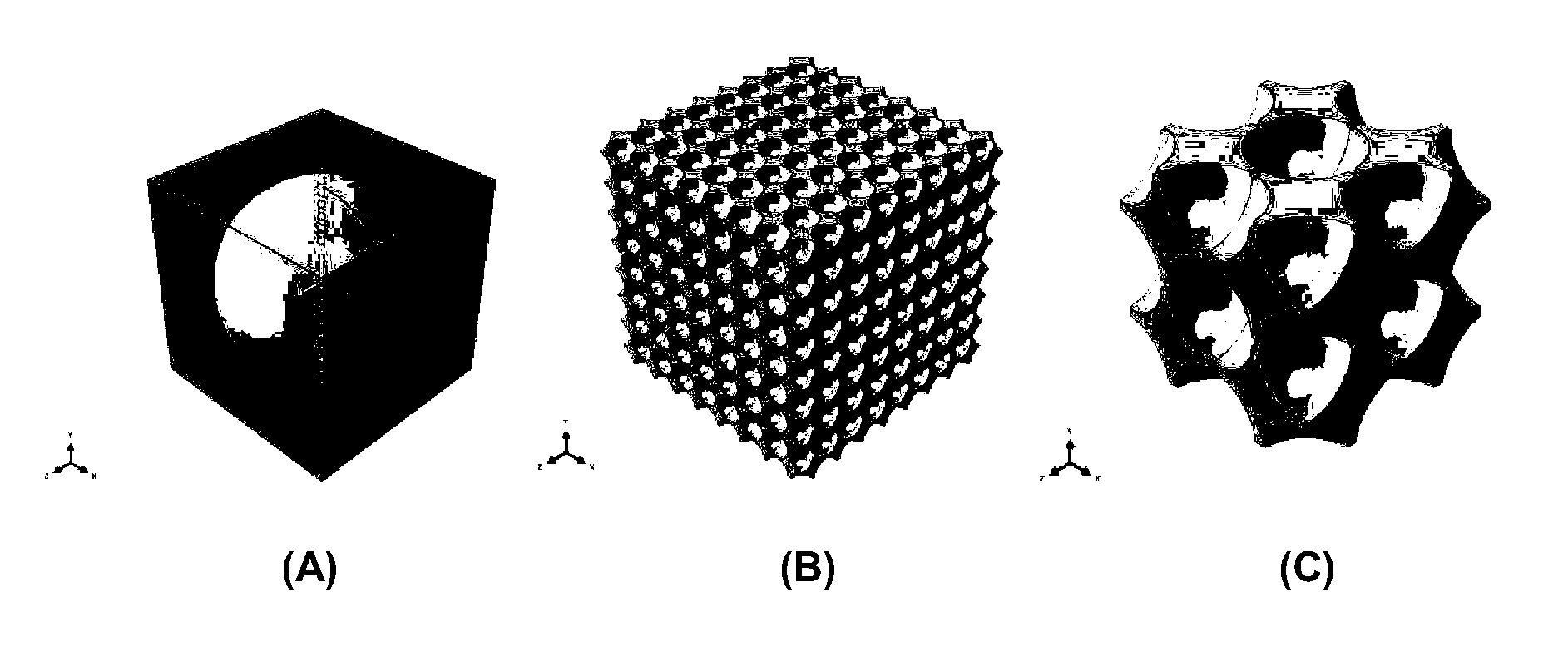
[0195]The geometry of the base cell for this example 3D auxetic metamaterial is formed by creating a hollow spherical cavity inside a cube, as shown in FIG. 1A(A) and FIG. 1B(A). Each of the building cells was repeated to form a 3D cellular material as respectively shown in FIG. 1A(B) and FIG. 1B(B). The experimental bulk metamaterial was constructed by repeating nine building cells along three normal directions and cut half of the both end-cells in each direction. Each of the specimens of the bulk 3D material were manufactured using 3D printing (ObjetConnex350) with a silicone-based rubber material (TangoPlus) and a supporting material.
[0196]According to the deformation pattern after buckling, the Representative Volume Element (RVE) contains four building cells as shown in FIG. 1A(C) and FIG. 1B(C). According to the ratio (R) of the diameter of the sphere to the length of the cube, two resultant geometry were established:[0197](1) a face-cen...
example 2
Mechanism Analysis (Buckling Mode)
[0207]Numerical simulations were carried out using the commercial finite element (FE) software package ABAQUS (Simulia, Providence, R.I.) to determine the mechanisms of the auxetic behaviour observed in the inventive metamaterial discussed in Example 1.
[0208]The ABAQUS / standard solver was employed for buckling analysis and ABAQUS / explicit solver was employed for postbuckling analyses. Quadratic solid elements with secondary accuracy (element type C3D10R with a mesh sweeping seed size of 0.4 mm) were used. The analyses were performed under uniaxial compression. The buckling mode with 3D alternating ellipsoidal pattern from buckling analysis was used as the shape change or imperfection factor for non-linear (large deformation) post-buckling analysis. The finite element models were validated using experimental results.
[0209]FIG. 4 shows the comparison of deformation process of the metamaterial from numerical simulation and experimental result from one ...
example 3
Cubic Base Cell with Ovoid Shaped Void
[0212]To overcome the buckling disadvantages of Example 1 and 2, the geometry of the base cell for this example 3D auxetic metamaterial is formed by creating a hollow ovoid cavity inside a cube, as shown in FIG. 6. The designed ovoid comprised an 8% imperfection in the shape of the spherical void used in the material discussed in Examples 1 and 2. In addition, the matrix of base units in the material was arranged such that the central length axis of the ovoid void of each base unit was perpendicular to the central length axis of the ovoid void of each adjoining base unit. This, in effect, introduced the pattern of the buckling mode seen in Examples 1 and 2 into the void pattern of this embodiment of the metamaterial. The porosity of this unit cell was found to be 87.4% for Example 1 and 87.2% for Example 2.
[0213]A direct comparison of nominal stress-strain curves between experimental and numerical results is shown in FIG. 5. Both curves exhibit ...
PUM
| Property | Measurement | Unit |
|---|---|---|
| Poisson's ratio | aaaaa | aaaaa |
| volume fraction | aaaaa | aaaaa |
| volume fraction | aaaaa | aaaaa |
Abstract
Description
Claims
Application Information