Wind turbine

Active Publication Date: 2017-01-12
NURIELECOM CO LTD
View PDF18 Cites 2 Cited by
  • Summary
  • Abstract
  • Description
  • Claims
  • Application Information

AI Technical Summary

Benefits of technology

[0010]An embodiment of the present disclosure provides a wind power generator including a flywheel, which increases a rotational inertia by inducing an electro

Problems solved by technology

However, since wind fluctuates significantly, the generation of electricity using conventional wind power generators may be sporadic.
In

Method used


Image

  • Wind turbine
  • Wind turbine
  • Wind turbine

Examples


Embodiment Construction

[0030]Hereinafter, specific embodiments will be described in detail with reference to the accompanying drawings. The present disclosure may, however, be embodied in different forms and should not be construed as limited to the embodiments set forth herein. Other embodiments may still be utilized and structural and functional modifications may be made without departing from the scope and spirit of the present disclosure.

[0031]Like reference numerals are used for referring to the same or similar elements in the description and drawings.

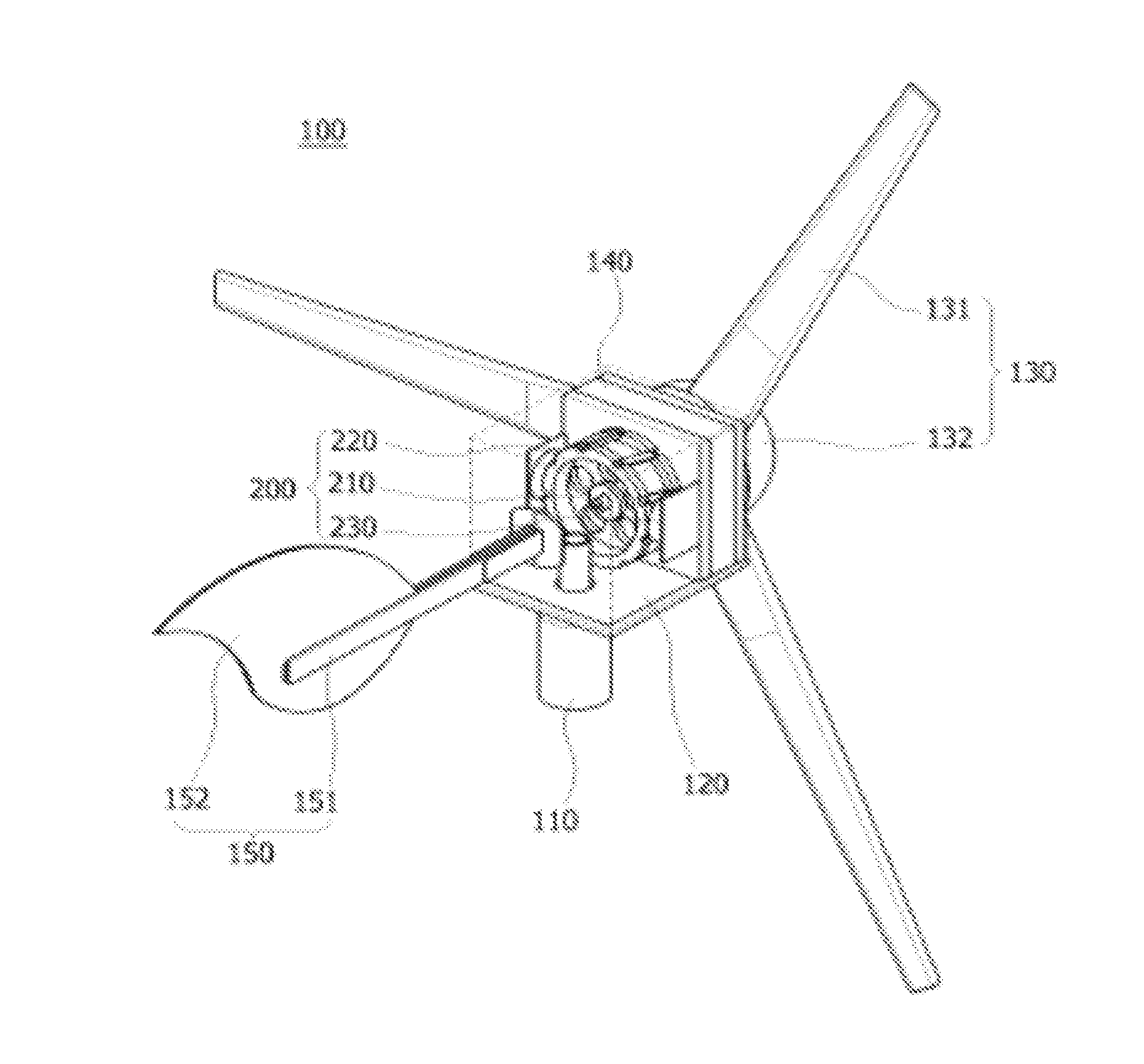
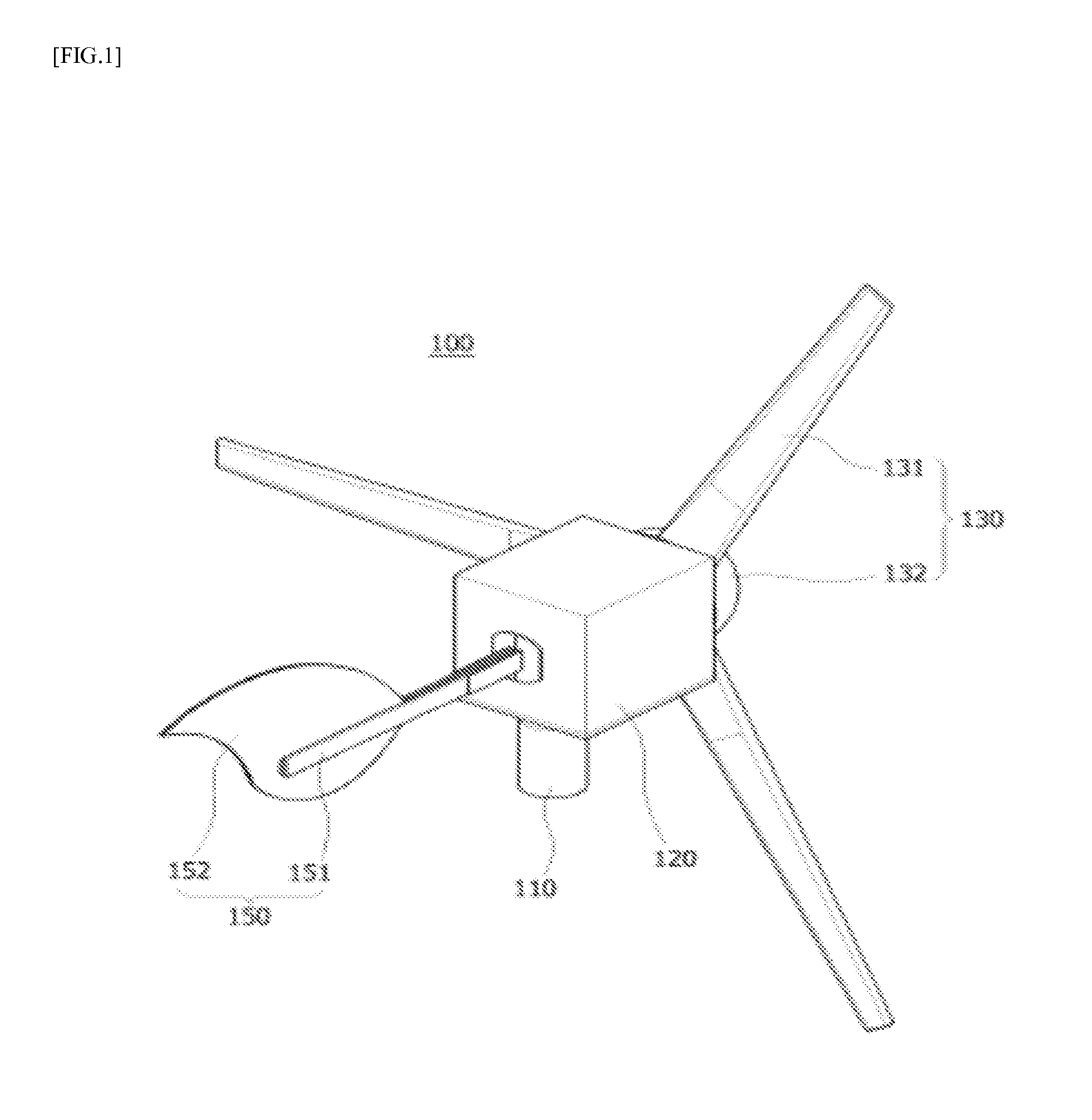
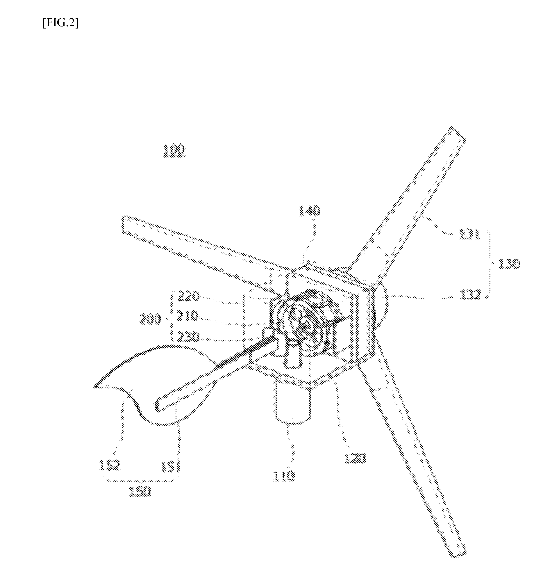
[0032]FIG. 1 is a perspective view of a wind power generator 100 including a flywheel 200 according to an embodiment of the present disclosure, and FIG. 2 is a perspective view illustrating the wind power generator 100 without a portion of a housing 120 according to an embodiment of the present disclosure.

[0033]Referring to FIGS. 1 and 2, the wind power generator 100 according to an embodiment of the present disclosure may include a support part 110, th...


PUM


Abstract

The wind generator includes a support part, a housing connected to an upper portion of the support part, the housing having an inner space, a blade part connected to one side of the housing, the blade part, an electricity generating part seated in the inner space of the housing, a flywheel, and a tail part. The flywheel includes a shaft rotating together with the blade part, a rotor coupled to the shaft, the rotor including at least one permanent magnet along an outer circumferential surface thereof, at least one coil part disposed outside in a radial direction of the rotor and around which a trigger coil is wound, the at least one coil generating magnetic fields when current is supplied to the trigger coil, and a circuit part supplying pulse-type current to trigger coil when the permanent magnet passes through a center of the trigger coil.

Description

CROSS-REFERENCE TO RELATED APPLICATION[0001]This application claims the benefit of Korean Patent Application No. 10-2015-0095738, filed on Jul. 6, 2015, which is hereby incorporated by reference in its entirety.BACKGROUND[0002]1. Field[0003]The present disclosure relates to a wind power generator. More particularly, the present disclosure relates to a wind power generator including a flywheel that increases a rotational inertia and an electromagnetic interaction through a pulse generating circuit.[0004]2. Discussion of the Background[0005]Recently, generating electricity using wind power has been heralded as form of clean energy, as well as photovoltaic power generation, hydroelectric power generation, and the like.[0006]In general, wind power generators include a rotation shaft attached to blades. When wind pushes the blades, the rotation shaft rotates. A generator may generate electricity from the mechanical energy of the rotation shaft.[0007]Since wind power generators generate e...

Claims


Application Information

Patent Timeline
IPC IPC(8): F03D9/00
CPCF03D9/002F05B2260/421F03D9/25Y02E10/72
Inventor PARK, SANG BOKLEE, JONG BAEKIM, IN DUK
Owner NURIELECOM CO LTD
Why Eureka
Try Eureka