Polar transmitter for RFID reader

Active Publication Date: 2017-01-12
CLAIRVOYANT TECH INC
View PDF1 Cites 21 Cited by
  • Summary
  • Abstract
  • Description
  • Claims
  • Application Information

AI Technical Summary

Problems solved by technology

However, there is typically a trade-off betw

Method used


Image

  • Polar transmitter for RFID reader
  • Polar transmitter for RFID reader
  • Polar transmitter for RFID reader

Examples


Embodiment Construction

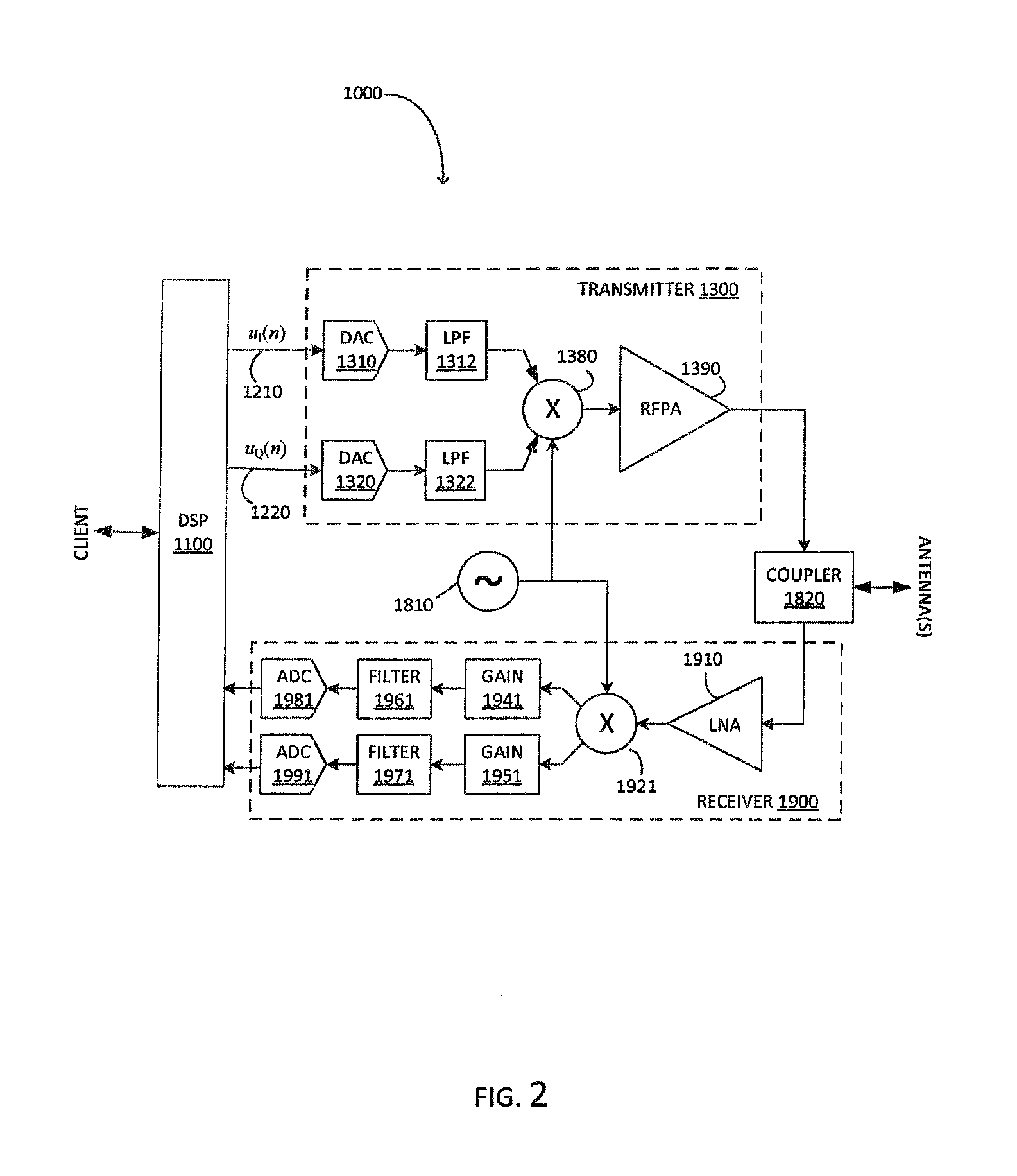
[0002]Embodiments of the present invention provide apparatus and methods for an improved RFID reader design using a polar transmitter. The apparatus according to embodiments of the invention can significantly improve the power efficiency and reduce the cost of the RFID reader. Embodiments of the invention, for example, may achieve power efficiencies of 66% or better. This can yield significant reductions in dissipated power with corresponding reductions in package size and cost as well as improved device reliability, since high temperatures due to dissipating power is often a cause of electronics failure. For example, a reader requiring RF power amplifier (RFPA) output of two watts using in a conventional quasi-linear class AB design at 33% efficiency will dissipate four watts of power internally. However, when using the polar transmitter design disclosed herein with 66% efficiency the RFPA would only dissipate one watt of power internally. The polar transmitter architecture disclos...


PUM


Abstract

A polar transmitter for an RFID reader and a system using the polar transmitter are disclosed. An RFID system according to at least some embodiments of the invention includes a polar transmitter employing a switch mode power amplifier. The system can also include a receiver to receive responses from RFID tags and a coupler connected to the polar transmitter, the receiver and one or more antennas. In at least some embodiments, the polar transmitter of the RFID system includes an envelope amplifier connected to the switch mode power amplifier to provide an envelope signal and a phase modulator connected to the switch mode power amplifier to phase modulate the switch mode power amplifier using a phase signal. In at least some embodiments, the polar transmitter of the RFID system transmits OPR-ASK signals to reduce AM modulation depth and provide a continuous phase signal for the phase modulator.

Description

BACKGROUND ART[0001]Radio frequency identification (RFID) is used in a wide variety of logistics, supply chain, manufacturing, and other applications. For some RFID protocols the reader may modulate commands onto a radio frequency (RF) carrier signal and the RFID tags respond to the modulated commands. The reader's modulation must include amplitude modulation because some RFID tag's commonly use envelope detection to decode the commands. The amplitude modulation requires that the reader's RF power amplifier (RFPA) be linear enough to pass regulatory and protocol conformance testing. However, there is typically a trade-off between RFPA linearity and RFPA power efficiency. To reduce cost and package size, the high performance RFID reader design must jointly optimize RFPA linearity and power efficiency. Many conventional RFID readers use class-AB RFPA designs for which linearity and power efficiency may be conflicting properties.DISCLOSURE OF EMBODIMENTS OF THE INVENTION[0002]Embodimen...

Claims


Application Information

Patent Timeline
IPC IPC(8): H04B5/00H04L27/04H04L25/49
CPCH04B5/0062H04L27/04H04L25/4902G06K7/10009H04L27/06
Inventor FREDERICK, THOMAS J.
Owner CLAIRVOYANT TECH INC
Why Eureka
Try Eureka