Method of inserting treatment tool

a treatment tool and tool body technology, applied in the field of treatment tools, can solve the problems of high difficulty in the method of inserting a treatment tool using this ercp

Active Publication Date: 2017-01-19
OLYMPUS CORP
View PDF6 Cites 3 Cited by
  • Summary
  • Abstract
  • Description
  • Claims
  • Application Information

AI Technical Summary

Benefits of technology

[0009]A method of inserting a treatment tool according to one aspect of the invention includes: making a puncture needle project from a first channel of an endoscope and puncturing an upper digestive tract to place a distal end of a needle tube of the puncture needle inside a biliary tract while observing an ultrasound image; inserting a guide wire into the biliary tract via the needle tube and making a distal end of the guide wire extend out from a duodenal papil

Problems solved by technology

However, the method of inserting a treatment tool by utilizing this ERCP is known as a highly difficult method among the

Method used


Image

  • Method of inserting treatment tool
  • Method of inserting treatment tool
  • Method of inserting treatment tool

Examples


embodiments

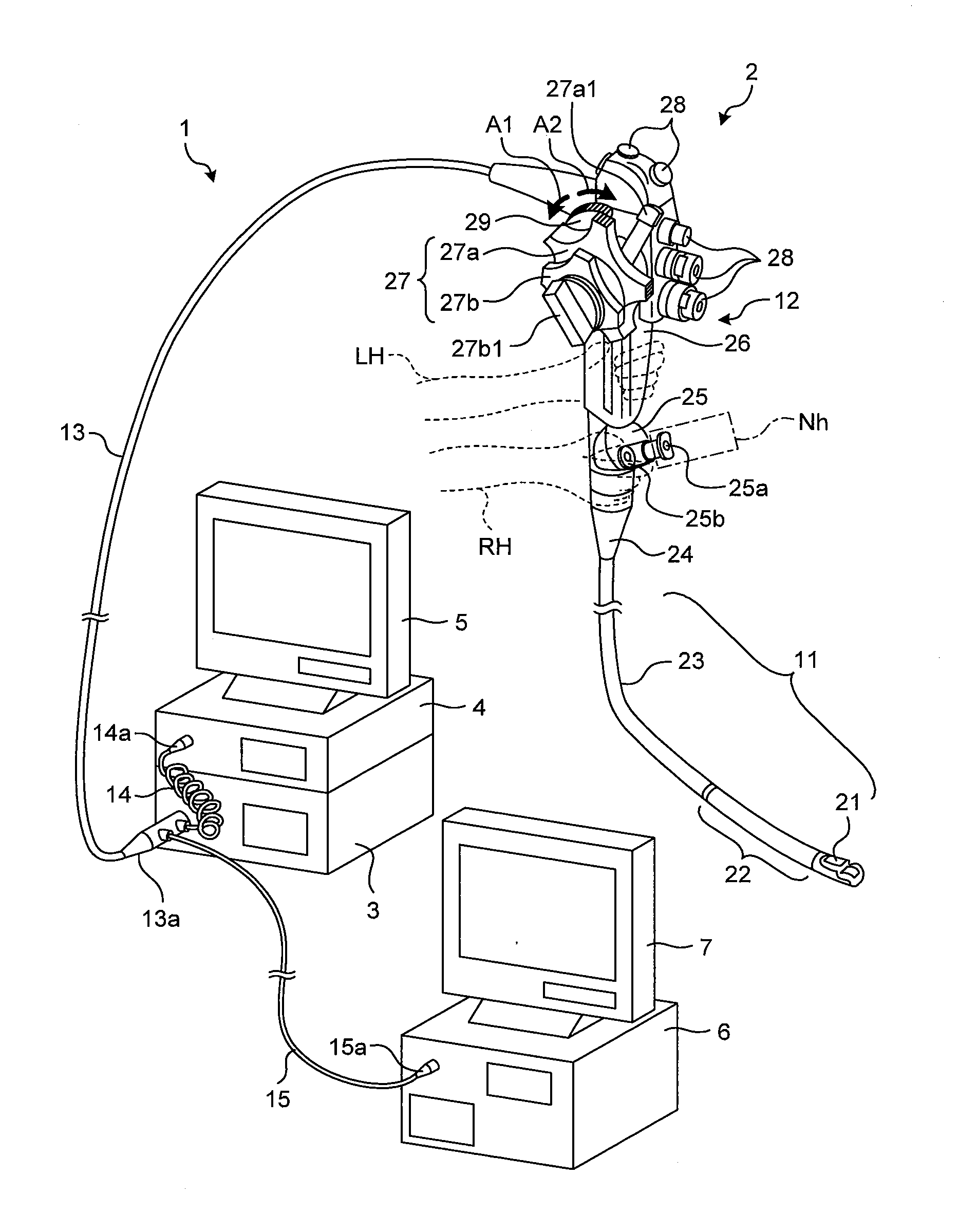
[0033]FIG. 7 is a schematic diagram illustrating a structure of an endoscope system according to an embodiment of the present invention. An ultrasound endoscope system 1 includes an ultrasound endoscope (hereinafter also referred to simply as an endoscope) 2, a light source device 3, a video processor 4, an optical image display monitor 5, an ultrasound observation device 6, and an ultrasound image display monitor 7.

[0034]The endoscope 2 includes an inserting portion 11, an operation unit 12 from which the inserting portion 11 extends, and a universal cord 13 extending from the operating unit 12. The inserting portion 11 extends in a longitudinal direction, and is formed so as to be inserted into a living body. The universal cord 13 is connected to the light source device 3 via a scope connector 13a disposed at a proximal end. A coiled scope cable 14 and an ultrasound signal cable 15 extend from this scope connector 13a. Further, an electric connector 14a is provided at one end of t...

modified example of embodiment

[0089]According to the above-described embodiment, the guide wire GW is kept extending from the duodenal papilla Dp by adjusting the extending amount of the guide wire GW from the duodenal papilla Dp even when the distal end portion 21 is moved, but not limited thereto. For example, the guide wire GW may be fed into the inserting portion 11 along with the movement of the distal end portion 21, and a predetermined amount of the guide wire GW may be made to extend between the duodenum Dd and the distal end portion 21 inside the duodenum Dd.

[0090]FIG. 20 is an explanatory diagram for a method of inserting a treatment tool using the endoscope system according to a modified example of the embodiment of the present invention, and is the explanatory diagram for operation of the guide wire GW. As illustrated in FIG. 20, the predetermined amount of the guide wire GW is extended inside the duodenum Dd. By this, even when the distal end portion 21 is moved, the extending amount of the guide wi...


PUM


Abstract

A method of inserting a treatment tool includes: making a puncture needle project from a first channel of an endoscope and puncturing an upper digestive tract to place a distal end of a needle tube of the puncture needle inside a biliary tract while observing an ultrasound image; inserting a guide wire into the biliary tract via the needle tube and making a distal end of the guide wire extend out from a duodenal papilla into a duodenum; placing a distal end portion of the endoscope in vicinity of the duodenal papilla while keeping the distal end of the guide wire extending out from the duodenal papilla while observing a captured image; pulling the guide wire extending out from the duodenal papilla into a second channel having a raised angle of the treatment tool larger than that of the first channel; and inserting the treatment tool inside the biliary tract via the guide wire.

Description

BACKGROUND OF THE INVENTION[0001]1. Field of the Invention[0002]The present invention relates to a method for inserting the treatment tool into a biliary tract from a digestive tract.[0003]2. Description of the Related Art[0004]In the related art, various kinds of endoscopes are used at the time of observing internal organs of a subject such as a patient. Among these endoscopes, there is a known ultrasound endoscope that transmits ultrasound waves to an observation target and receives echoes of the ultrasound waves reflected at the observation target. An ultrasound image of the observation target is generated by applying predetermined signal processing to the ultrasound echoes received by the ultrasound endoscope, thereby achieving to perform diagnosis and treatment while observing the ultrasound image.[0005]As a treatment method using the ultrasound endoscope, there is a method of inserting a treatment tool in which the treatment tool is inserted into a stenosis at a biliary tract ...

Claims


Application Information

Patent Timeline
IPC IPC(8): A61B17/00A61B8/12A61B1/06A61B1/273A61B1/018A61B1/04
CPCA61B17/00234A61B1/018A61B1/04A61B2017/00278A61B1/2736A61B8/12A61B1/06A61F2/95A61B2017/00818A61B8/0841A61F2/04A61F2002/045A61B1/00098A61B1/273A61M2025/018A61M2025/0183
Inventor NAKAZATO, TAKEHARU
Owner OLYMPUS CORP
Why Eureka
Try Eureka