Joint brick for building block

a technology of building blocks and joints, applied in the field of joints for building blocks, can solve the problems of not being able to achieve the effect of substantially swinging, extending or bending relative to each other, and the interlocking structure of conventional building blocks still has some disadvantages

Inactive Publication Date: 2017-01-19
T FUN
View PDF5 Cites 9 Cited by
  • Summary
  • Abstract
  • Description
  • Claims
  • Application Information

AI Technical Summary

Benefits of technology

[0007]A primary objective of the present invention is to provide a joint brick for a building block, and particular to a joint brick pivotally connected between the building blocks to work as a joint of a limb. Therefore, the joint brick according to the present invention overcomes the disadvantage of the conventional building blocks which use the studs and engaging recesses to connect the building blocks with each other and thus can not substantially swing, extend and bend between the building blocks that work as limbs.

Problems solved by technology

However, the interlocking structure of the conventional building blocks still has some disadvantages.
For example, when assembling the building blocks to form a robot having movable limbs (hands or legs), an insect or an animal and the like, the conventional stud-and-engaging-recess interlocking structure can not achieve that the limbs can substantially swing, extend or bend relative to each other.
However, these topics are not disclosed yet.

Method used


Image

  • Joint brick for building block
  • Joint brick for building block
  • Joint brick for building block

Examples


first embodiment

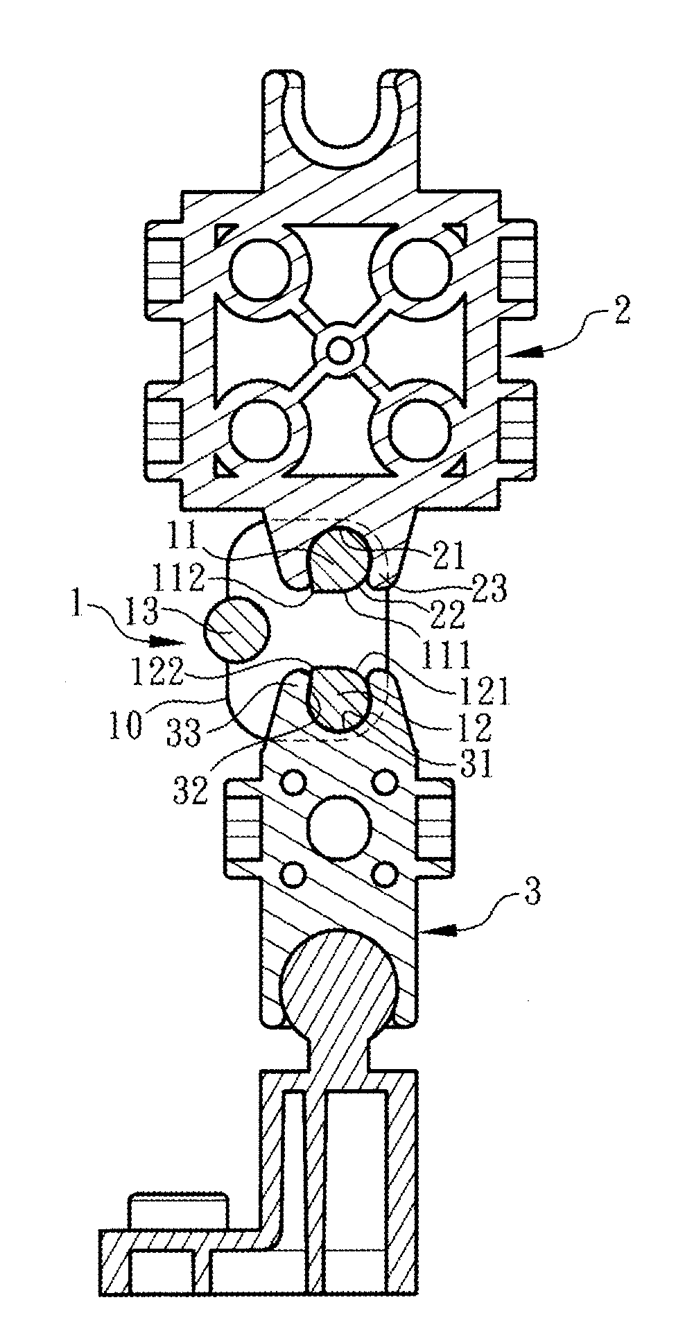
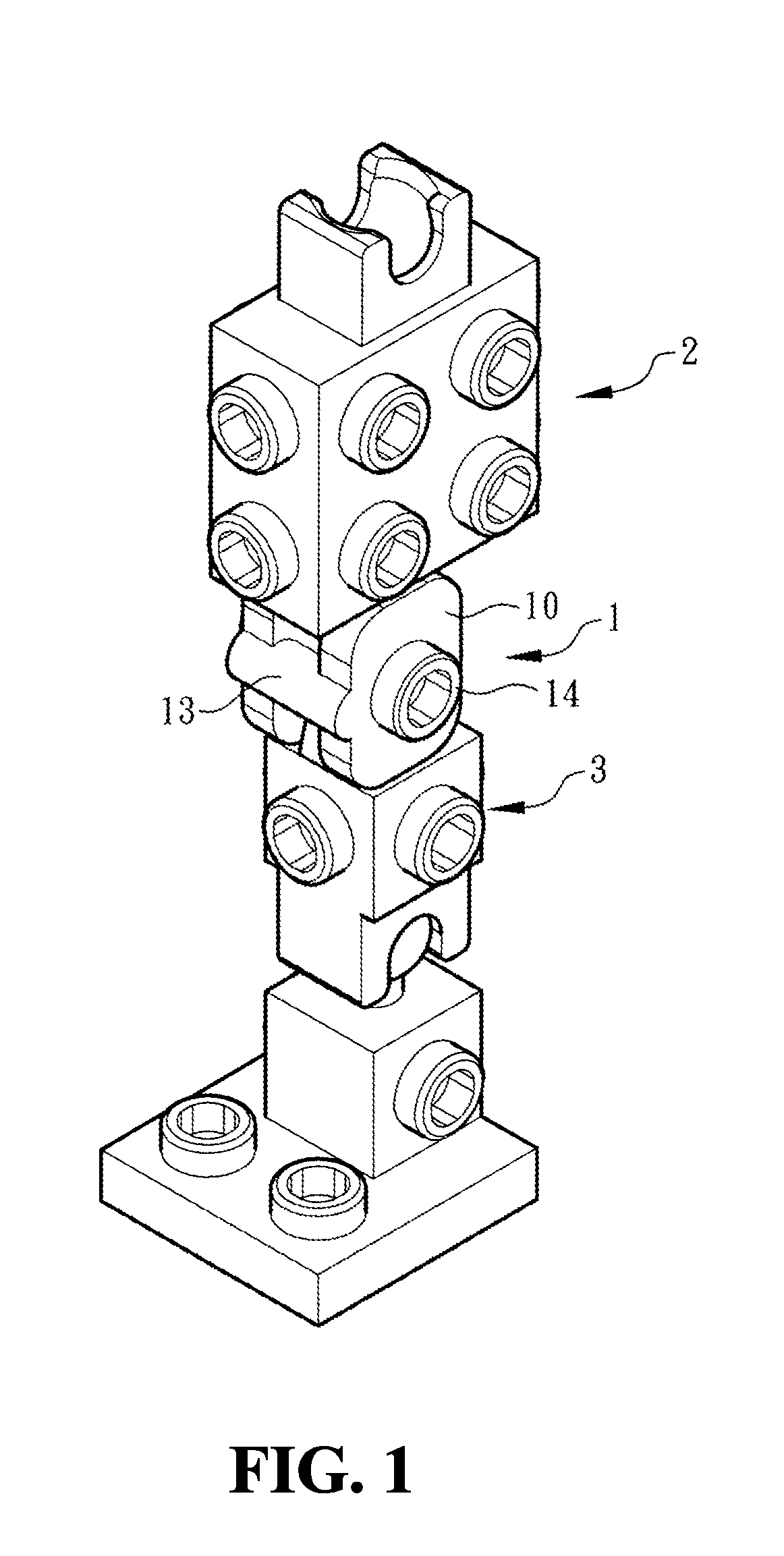
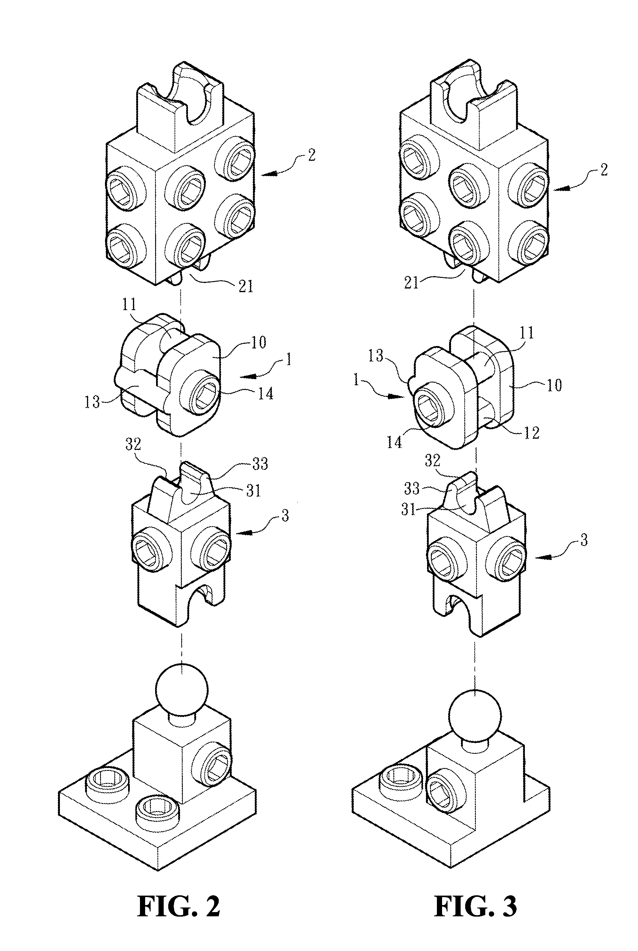
[0027]When connecting the building blocks to form robots having movable limbs (hands or legs), insects or animals, etc, both ends of the joint brick 1 are respectively acted as a top end and a bottom end due to the first axial post 11 and the second axial post 12 respectively located at the top end and the bottom ends of the joint brick 1. the present invention gives an example that the building blocks are assembled to form a limb (a movable lower or upper limb) of a robot. A thigh brick 2 having engaging recesses 21 is provided at the top end of the joint brick 1, and the engaging recess 21 disposed at the bottom end of the thigh brick 2 is engaged with the first axial post 11 disposed at the top end of the joint brick 1. The engaging recess 21 of the thigh brick 2 can be a conventional engaging recess. The engaging recess 21 is shaped in a groove and provided with a recess opening 22 and two outer edge portions 23 disposed at two sides of the recess opening 22, so that the thigh b...

second embodiment

[0032]Referring to FIGS. 6 and 7, according to the present invention, the joint brick 1 is further engaged with a front knee brick 4 having a conventional engaging recess 41. The engaging recess 41 of the front knee brick 4 is engaged with the engaging shaft 13 of the joint brick 1 and outer edge portions 43 disposed at two sides of the engaging recess 41 are inserted into the space between the two side plates 10, thereby connecting the front knee brick 4 with the joint brick 1. The front knee brick 4 also provides an encasing function for the front of the joint brick 1. The front knee brick 4 may further include a decoration portion 40 disposed at a side opposite to the engaging recess 41 to work as an exterior structure of the robot, the insect, the animal, and the like. Therefore, the appearance of the connected building blocks can be changed according to the designs of the decoration portion 40. It makes connecting the building blocks easier, more convenient and more interesting...


PUM


Abstract

A joint brick for a building block is pivotally connected between the building blocks to work as a joint of the limbs. The joint brick includes two side plates and two axial post disposed between the side plates to be pivotally connected with engaging recesses of other building blocks. When the axial posts disposed at a top end and a bottom end of the joint brick are pivotally connected with other building blocks, the limbs can substantially swing, extend and bend relative to each other to make playing the building blocks more convenient and more interesting.

Description

BACKGROUND OF THE INVENTION[0001]1. Field of the Invention[0002]The present invention relates generally to a joint brick for a building block, such as Lego bricks and Mega Bloks bricks, and more particularly, to provide a joint brick pivotally connected between the building blocks to work as a joint of a limb.[0003]2. The Prior Arts[0004]Building blocks are toys that can train hand eye coordination, enhance the development of intelligence and develop children's imagination and creativity. Therefore, the building blocks are popular and widely favored by the consumers. Currently, the most successful construction toy in the world is generally considered to be the Lego bricks, which are manufactured by The Lego Group, a company having a history of 50 years and based in Denmark. The Lego Group not only has the most customers and the largest market share in the world but also has the largest forum, creators and players. Therefore, Lego become a synonym for the building blocks. Because man...

Claims


Application Information

Patent Timeline
Patent Type & Authority Applications(United States)
IPC IPC(8): A63H33/08
CPCA63H33/08A63H3/16A63H3/46A63H33/042A63H33/086A63H33/101
Inventor CHEN, TSAI-TILEE, HERO
Owner T FUN
Why Eureka
Try Eureka