Method of manufacturing packing and packing

a manufacturing method and packing technology, applied in the field of manufacturing packing and packing, can solve the problems of reduced contact area between reduced chemical reaction amount of the reaction liquid and the separation target gas, and easy increase of so as to reduce the weight of the packing

Active Publication Date: 2017-01-19
IHI CORP
View PDF0 Cites 7 Cited by
  • Summary
  • Abstract
  • Description
  • Claims
  • Application Information

AI Technical Summary

Benefits of technology

[0018]According to the method of manufacturing the packing and the packing of the present disclosure described above, the design conditions of the rib are determined based on the correlation between the contact angle of the rib and the liquid film length ratio, and thus it is possible to adjust the contact angle of the rib to be such

Problems solved by technology

However, the reaction liquid may not uniformly flow on the surface of the packing due to the effect of surface tension, and the liquid film of the reaction liquid flowing on the surface of the packing converges (hereinafter referred to as “liquid film rupture” or “liquid filmbreak up”), with the result that the contact area between the reaction liquid and the separation target gas may be reduced.
Consequently, there has been such a problem that the chemical reaction amount of the reaction liquid and the separation target gas is decreased.
However, in the packing of the tubular structure as disclosed in Patent Literatures 1 and 2 described above, there has been such a problem that the weight of the packing is easily increased, and thus the weight or size of the entire device is increased.
Moreover, there has been such a problem that the flow path of a gas for the packing is easily narrowed, and thus the size of the entire device is increased in order to ensure the area of the gas flow path.
Furthermore, in the packing of the plate-like member as disclosed in Patent Literature 2, there

Method used


Image

  • Method of manufacturing packing and packing
  • Method of manufacturing packing and packing
  • Method of manufacturing packing and packing

Examples


Embodiment Construction

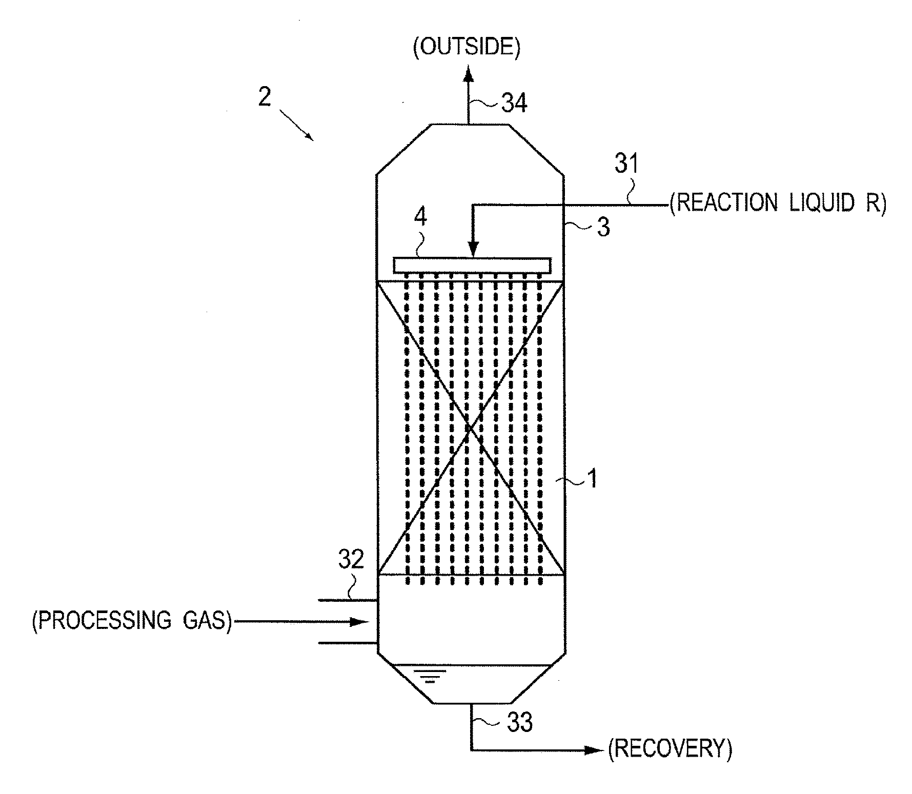
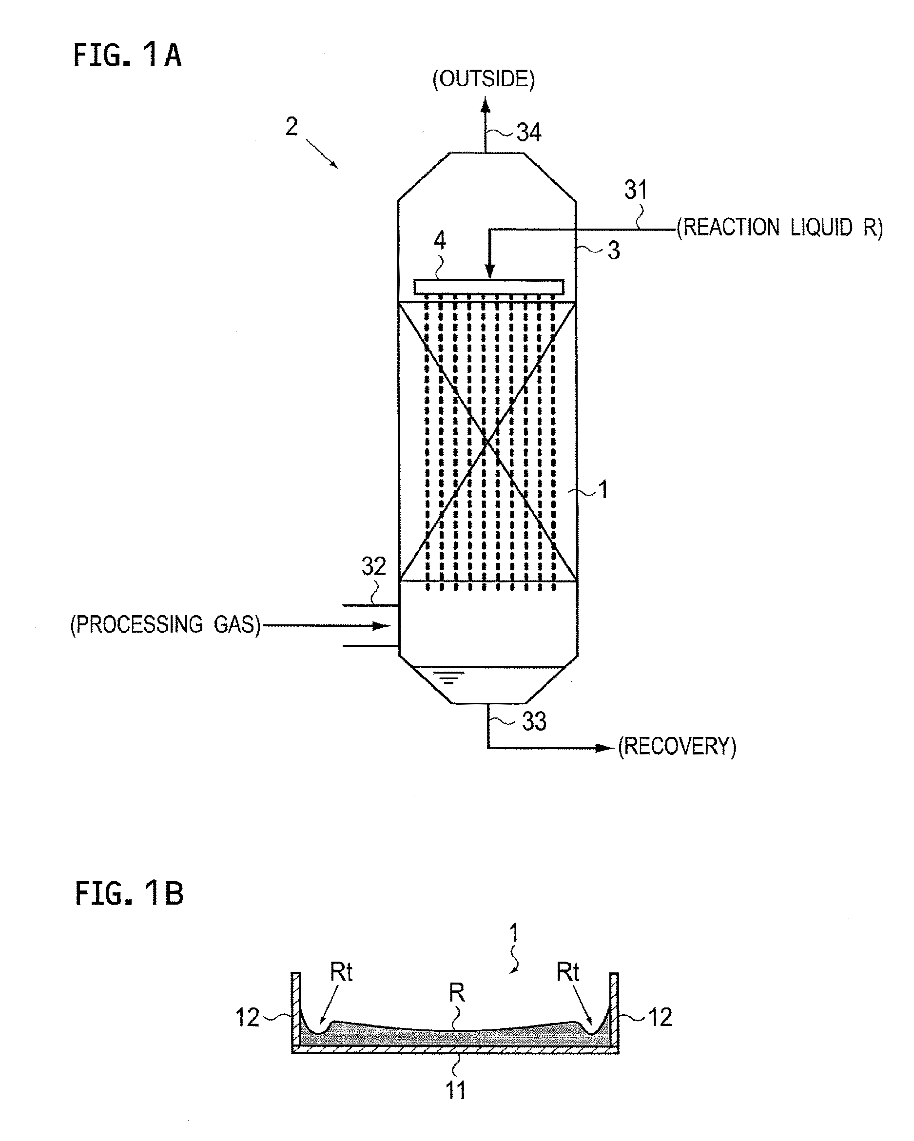
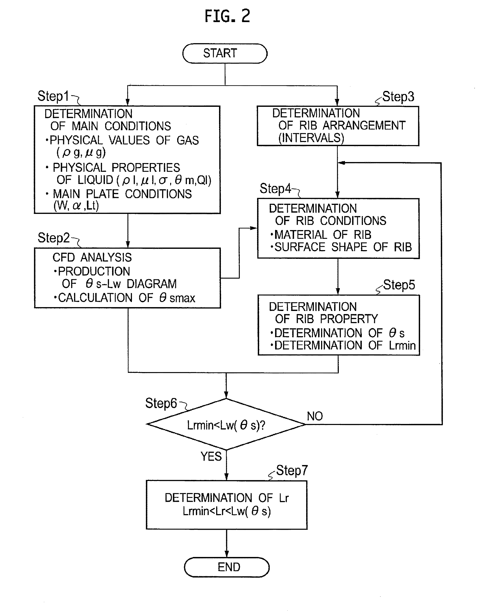
[0026]An embodiment of the present disclosure will be described below with reference to FIGS. 1A to 7B. Here, FIGS. 1A and 1B are diagrams showing a gas separation device using packing according to the present embodiment, and show an overall configuration diagram and a cross-sectional view of the packing, respectively. FIG. 2 is a flow diagram showing a method of manufacturing the packing according to the present embodiment.

[0027]In the gas separation device 2 using the packing 1 according to the present embodiment, as shown in FIG. 1A, a reaction liquid R is made to flow downward on the surface of the plate-like packing 1 arranged within a reaction container 3, and a processing gas containing a separation target gas is supplied into the reaction container 3. While the reaction liquid R flows downward on the surface of the packing 1, a liquid film of the reaction liquid R is formed on the surface. The processing gas within the reaction container 3 makes contact with the liquid film ...


PUM

PropertyMeasurementUnit
Contact angleaaaaaaaaaa

Abstract

A method of manufacturing packing includes: determining types of a gas and a liquid which are brought into gas-liquid contact and a main plate to be used; calculating a relationship between a contact angle and a liquid film length ratio; determining the arrangement (intervals) of a rib; determining rib conditions; calculating the minimum value of the flow direction length of the rib satisfying the contact angle and a strength requirement; confirming whether or not a liquid film length is greater than the minimum value; and determining the flow direction length of the rib within a range from the minimum value to the liquid film length.

Description

CROSS REFERENCE TO RELATED APPLICATIONS[0001]This application is a continuation application of International Application No. PCT / JP2015 / 058810, filed on Mar. 24, 2015, which claims priority to Japanese Patent Application No. 2014-075098, filed on Apr. 1, 2014, the entire contents of which are incorporated by reference herein.BACKGROUND[0002]1. Technical Field[0003]The present disclosure relates to a method of manufacturing packing and packing, and more particularly relates to a method of manufacturing packing which is suitable for a gas separation device that makes a separation target gas such as carbon dioxide contained in a processing gas such as an exhaust gas chemically react with a reaction liquid so as to separate or recover it and to packing.[0004]2. Description of the Related Art[0005]Conventionally, in a chemical plant, a thermal power plant and the like, gas separation devices (for example, a distillation tower, an absorption tower and a purification tower) are used which ...

Claims


Application Information

Patent Timeline
IPC IPC(8): B01J19/32B01D3/00B01D53/14B01D53/18B01D53/78B01D53/62
CPCB01J19/32B01D53/78B01D53/62B01D53/1475B01D53/185B01D3/008B01D2258/0283B01J2219/3221B01J2219/32213B01J2219/32227B01J2219/32251B01J2219/32408B01J2219/328B01J2219/32206B01J19/247B01D2252/20484B01D2257/302B01D2257/404B01D2257/504B01D1/007B01D1/0064Y02C20/40
Inventor ISO, YOSHIYUKIHUANG, JIANSAGA, MARIKOMATSUNO, SHINSUKEUCHIDA, HIROYUKIFUJIWARA, NAOKITAKANO, KENJITOKUDA, KENJI
Owner IHI CORP
Why Eureka
Try Eureka