Well abandonment using vibration to assist cement placement

a technology of vibration and cement placement, which is applied in the direction of earth-moving drilling, well accessories, sealing/packing, etc., can solve the problems of time-consuming and expensive removal of xmas trees and production tubing, inability to achieve a practical technique, and inability to achieve cost advantages, etc., to achieve the effect of maximizing the vibration degr

Active Publication Date: 2017-01-19
CONOCOPHILLIPS CO
View PDF4 Cites 18 Cited by
  • Summary
  • Abstract
  • Description
  • Claims
  • Application Information

AI Technical Summary

Benefits of technology

[0031]Whatever means is used to cause the vibration or reciprocal movement of the tubing, the degree of vibration may be maximized by tuning the vibrational input (including pulsing of cement) to the harmonics of the tubing, e.g. causing the tubing to vibrate at or near a resonant frequency. The frequency of vibration may be tuned, e.g. by changing the design of the agitator, changing the diameter of a choke, changing the frequency of an oscillating power source, etc.

Problems solved by technology

When an oil or gas well is no longer economical or if there is some problem with the well which means that production is no longer possible or that well integrity has been compromised in some way, or for other reasons, the well may be abandoned.
However, removal of the Xmas tree and production tubing is time consuming and expensive and another theoretical approach is to deliver cement through the production tubing without removing either tubing or Xmas tree.
The cost advantages of this technique, if it can be achieved, would be considerable.
Unfortunately, a cement barrier formed using this technique is often found to be inadequate and therefore the technique is not a practical one.
Without wishing to be bound by theory, the inventors believe the main reason for this is that the production tubing is not usually centrally positioned in the casing and, due to its viscosity, the cement may not be able to pass between the casing and tubing when they are close together or in contact.
The length and flexibility of the tubing are such that it inevitably rests against the inside of the casing over a large proportion of its length.
Without wishing to be bound by theory, the inventors believe this is why the resulting cement plug tends not to form a fully isolating radial bond around the tubing, or at least not over a sufficient length of the tubing.
There may also be other reasons why the cement barrier is found to be inadequate, which may not at present be understood fully by the inventors.
However, there remains a significant un-met need for a reliable cementing technique which will allow a plug and abandon operation to be performed without removal of the Xmas tree and production tubing.

Method used


Image

  • Well abandonment using vibration to assist cement placement
  • Well abandonment using vibration to assist cement placement
  • Well abandonment using vibration to assist cement placement

Examples


example 1

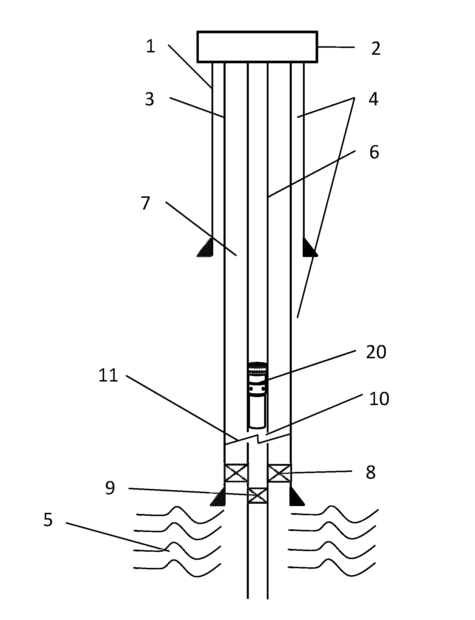
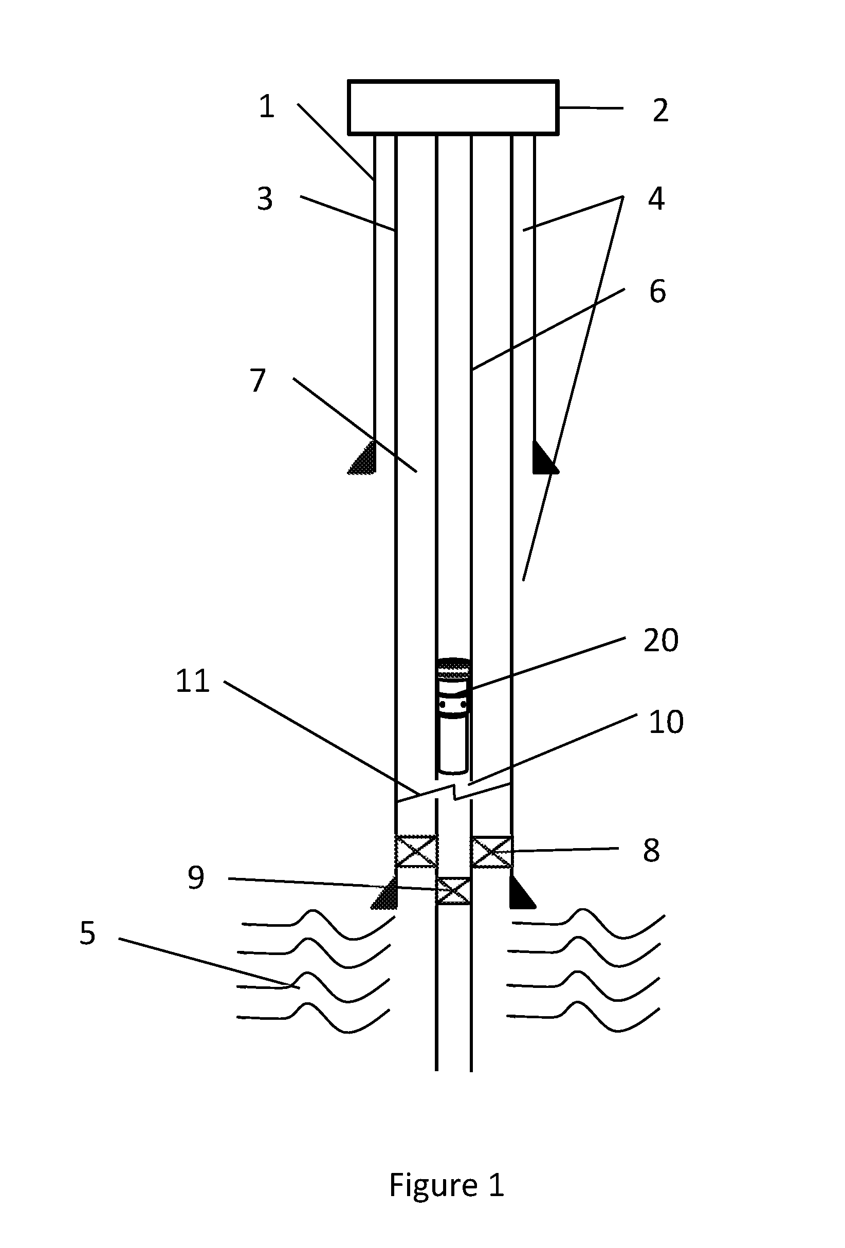
[0069]An onshore trial was performed to assess the feasibility of the agitator assembly comprising a packer and agitator device under operational conditions and to assess the extent of tubing movement generated by the agitator. 9⅝″ casing was run into a test well to approximately 3,200 ft and filled with heavy mud with similar properties to cement used in abandonments. Approximately 3,000 ft of 5½″ tubing was then run into the hole with a pre-set packer and agitator in the tubing. Two black box subs were also installed in the string at 1,000 ft and 2,000 ft behind the agitator. The subs contained accelerometers to record any lateral or axial acceleration generated. The 5½″ tubing was then locked down to simulate a through-tubing abandonment.

[0070]The heavy mud was then pumped around the well at varying flow rates between 110-210 gallons per minute for an extended duration of approximately 6.5 hours. Pressure indications on surface indicated that the agitator was pulsing throughout t...

example 2

[0071]Following successful onshore trials, the focus was moved to performing offshore trials. 3,000 ft of 5½″ open-ended tubing was cemented into 9⅝″ casing under static conditions in Well 1. Cement was placed into the A annulus and final displacement pressure was held to prevent cement from flowing back inside the tubing, meaning the interior of the tubing was left clear. The cement in the A annulus was then logged to assess quantity and quality. The result of this log showed that there was 733 ft out of 2,000 ft of cement that can be termed as acceptable for abandonment purposes.

example 3

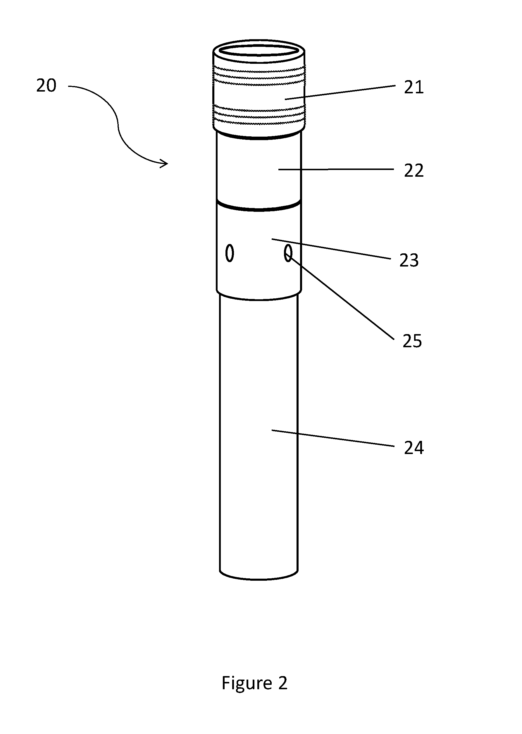
[0072]A similar trial was repeated on Well 2 but this time, a similar packer and agitator assembly to the one used in the onshore trial was run into the 5½″ tubing on wire line and set at the bottom of the tubing. 2,000 ft of cement was then pumped through the agitator and into the A annulus. Again, final displacement pressure was held to prevent cement from flowing back inside the tubing, leaving the inside of the tubing clear. The results were then logged for quality and quantity. The results showed that the cement quality was poor and only 10 ft was deemed to be acceptable for abandonment purposes. It is uncertain whether these bad results were due to the poor integrity of the production tubing in this well or the fact no base plug was set for the cement. Either of these are considered by the inventors to be possible causes, or there may be another cause. There is also the possibility that human or mechanical error contributed towards the poor result.


PUM


Abstract

A method of cementing an oil or gas well for abandonment comprises cutting the production tubing 6 above the production packer 8, setting a tubing plug 9 in the tubing and then cutting the tubing. A bridge plug may be installed at the level of the cut, which spans the full diameter of the well casing 3. An agitator assembly 20 comprising an agitator 24, packer 21 and burst sub 23, with a running tool fitted to the top, is run down the tubing on wire line. Cement is then injected into the tubing 6, which flows through the agitator assembly and causes the tubing to vibrate. The cement fills the tubing but also flows back up the A annulus between the casing and production tubing. Vibration of the tubing assists the formation of a good quality cement plug extending all around the annulus over a substantial length of the well.

Description

CROSS-REFERENCE TO RELATED APPLICATIONS[0001]This application is a non-provisional application which claims benefit under 35 USC §119(e) to U.S. Provisional Application Ser. No. 62 / 193,801 filed Jul. 17, 2015, entitled “WELL ABANDONMENT USING VIBRATION TO ASSIST CEMENT PLACEMENT,” which is incorporated herein in its entirety.STATEMENT REGARDING FEDERALLY SPONSORED RESEARCH OR DEVELOPMENT[0002]None.FIELD OF THE INVENTION[0003]This invention relates to the abandonment of oil and gas wells and specifically to the plugging of wells using cement or other settable medium, e.g. when they have reached the end of their productive life. The invention also relates to a device for plugging a well and to a plugged well.BACKGROUND OF THE INVENTION[0004]When an oil or gas well is no longer economical or if there is some problem with the well which means that production is no longer possible or that well integrity has been compromised in some way, or for other reasons, the well may be abandoned. It...

Claims


Application Information

Patent Timeline
Patent Type & Authority Applications(United States)
IPC IPC(8): E21B33/138E21B33/134E21B29/00E21B33/12E21B28/00
CPCE21B33/138E21B33/12E21B33/134E21B29/002E21B28/00E21B33/13
Inventor PRIEUR, JEAN-MARIEHOOD, ANDREWMILNE, IANCROMAR, STEPHEN
Owner CONOCOPHILLIPS CO
Why Eureka
Try Eureka