
Antenna input tuning circuit

a technology of input tuning and antenna input, which is applied in the direction of resonance circuit tuning, pulse automatic control, electrical equipment, etc., can solve the problems of difficult to accurately adjust the tuning frequency, noise from the mosfet itself, and the inability to change the tuning frequency beyond the variation of the gate-source voltage vgs, so as to reduce the number of external components, reduce the shift from the desired received frequency, and facilitate the integration of the antenna input tuning circuit

Inactive Publication Date: 2009-10-08
NEURO SOLUTION CORP
View PDF8 Cites 5 Cited by
  • Summary
  • Abstract
  • Description
  • Claims
  • Application Information

AI Technical Summary

Benefits of technology

[0014]In order to solve the problems, it is an object of the present invention to enable the number of external components to be decreased when integrating an antenna input tuning circuit employing a digital tuning method.
[0015]Moreover, it is another object of the present invention to suppress a variation in a characteristic due to a manufacturing process and a generation of a noise, thereby enabling a tuning frequency to be adjusted more accurately.
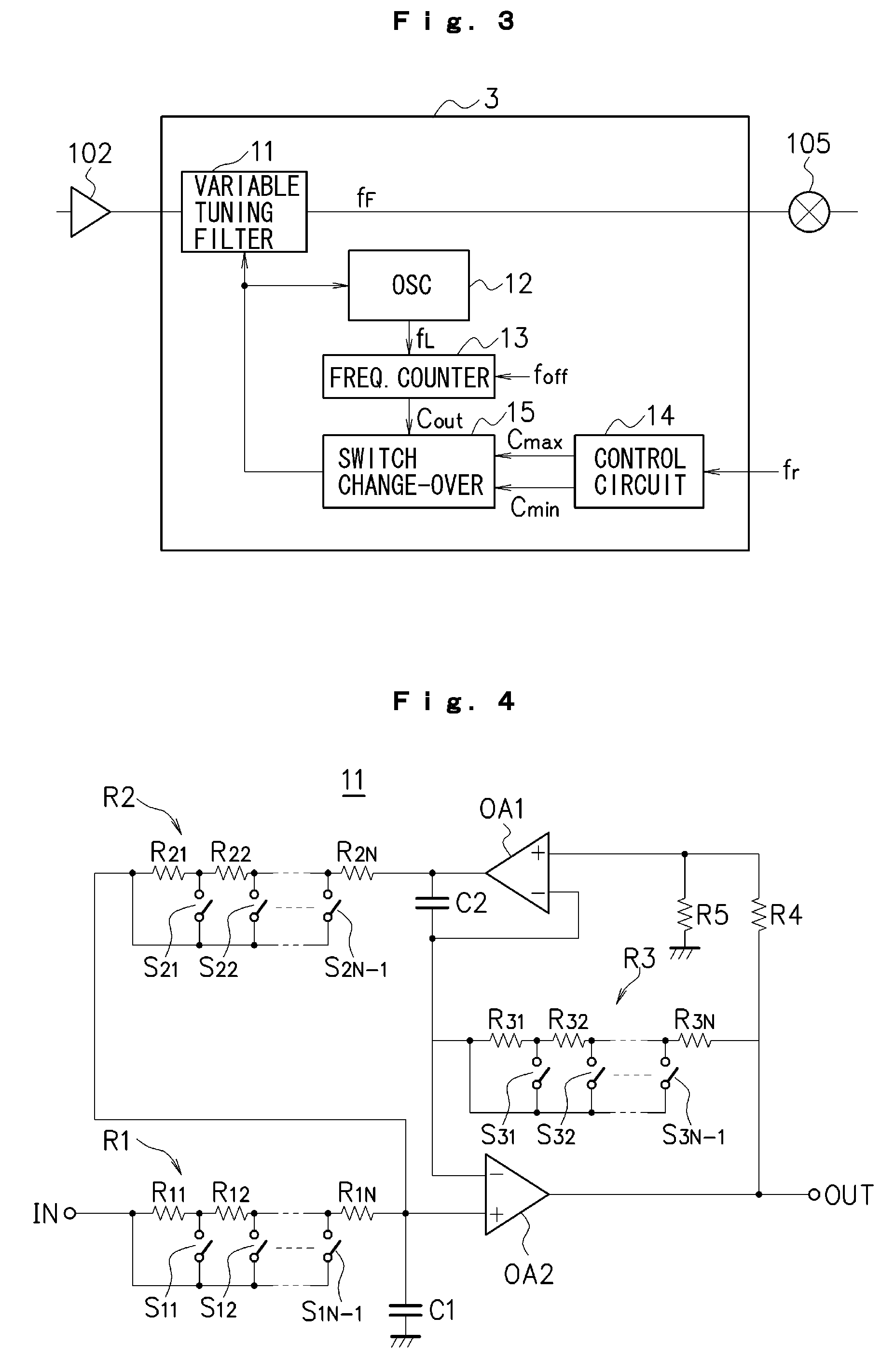
[0018]According to the present invention having the structure described above, the oscillating frequency of the oscillating circuit which is monitored by the frequency counter and a preset desirable received frequency are digitally compared with each other based on the count value and the oscillating frequency of the oscillating circuit is set to be variable by changing over the switch in such a manner that both of the frequencies are coincident with each other (a predetermined error range may be permitted), and the tuning frequency of the variable tuning filter is correspondingly set to be variable by changing over the switch. The variable tuning filter and the oscillating circuit are formed on the same semiconductor chip. Therefore, both variations in characteristics are generated in the same direction. By monitoring the oscillating frequency of the oscillating circuit to adjust the tuning frequency and similarly adjusting the tuning frequency in the variable tuning filter, accordingly, it is possible to reduce a shift from the desirable received frequency.
[0019]The oscillating circuit and the variable tuning filter have the same structures and both of them are constituted by the RC active filter, and it is not necessary to use a variable capacitor and a variable capacitance diode which are hard to integrate. Consequently, it is possible to decrease the number of the external components and to easily integrate the antenna input tuning circuit and the radio receiver using the antenna input tuning circuit. According to the present invention, moreover, the MOSFET-C filter is not used. Therefore, it is also possible to improve the problems of the dynamic range, the variation in a characteristic due to a manufacturing process and an FET noise.
[0020]According to another feature of the present invention, furthermore, the variable tuning filter and the oscillating circuit are disposed close to each other. Therefore, the variation in a characteristic due to a manufacturing process between the variable tuning filter and the oscillating circuit can be reduced more greatly. Consequently, it is possible to reduce a shift between the tuning frequency adjusted by monitoring the oscillating frequency of the oscillating circuit and the desirable received frequency, thereby controlling the tuning frequency of the antenna input tuning circuit more accurately.
[0021]According to a further feature of the present invention, a predetermined amount of offset is added to the oscillating frequency of the oscillating circuit to carry out a counting operation. Consequently, it is possible to cause the oscillating frequency of the oscillating circuit and the tuning frequency of the variable tuning filter to have a difference. In the case in which the variable tuning filter and the oscillating circuit which have the same circuit structures are disposed close to each other, a signal oscillated by the oscillating circuit is sent around the variable tuning filter to make a noise if the oscillating frequency of the oscillating circuit is equal to the tuning frequency of the variable tuning filter. On the other hand, it is possible to suppress an occurrence of the noise by causing the oscillating frequency of the oscillating circuit and the tuning frequency of the variable tuning filter to have a difference.

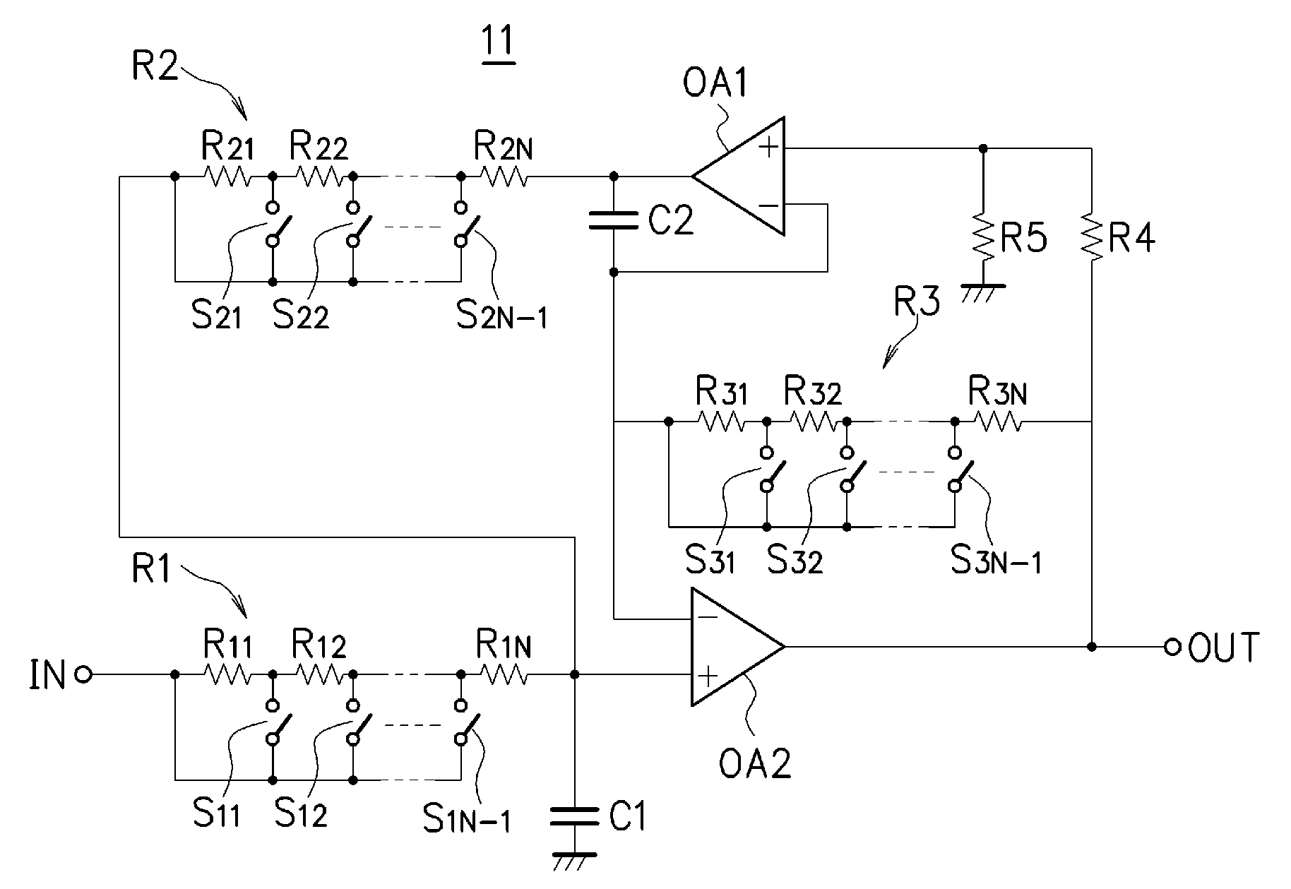
Problems solved by technology

In the case in which the tuning circuit is constituted by the MOSFET-C filter, however, the tuning frequency cannot be changed beyond a variation in the gate-source voltage Vgs.
Moreover, an ON resistance of the MOSFET has a great variation in a characteristic due to a manufacturing process and the tuning frequency is hard to adjust accurately.
Furthermore, there is also a problem in that a noise is made from the MOSFET itself.
Thus, the conventional radio receiver using the digital method has a problem in that the number of the external components is increased in the integration and a cost is thus increased.

Method used


Image

  • Antenna input tuning circuit
  • Antenna input tuning circuit
  • Antenna input tuning circuit

Examples


Embodiment Construction

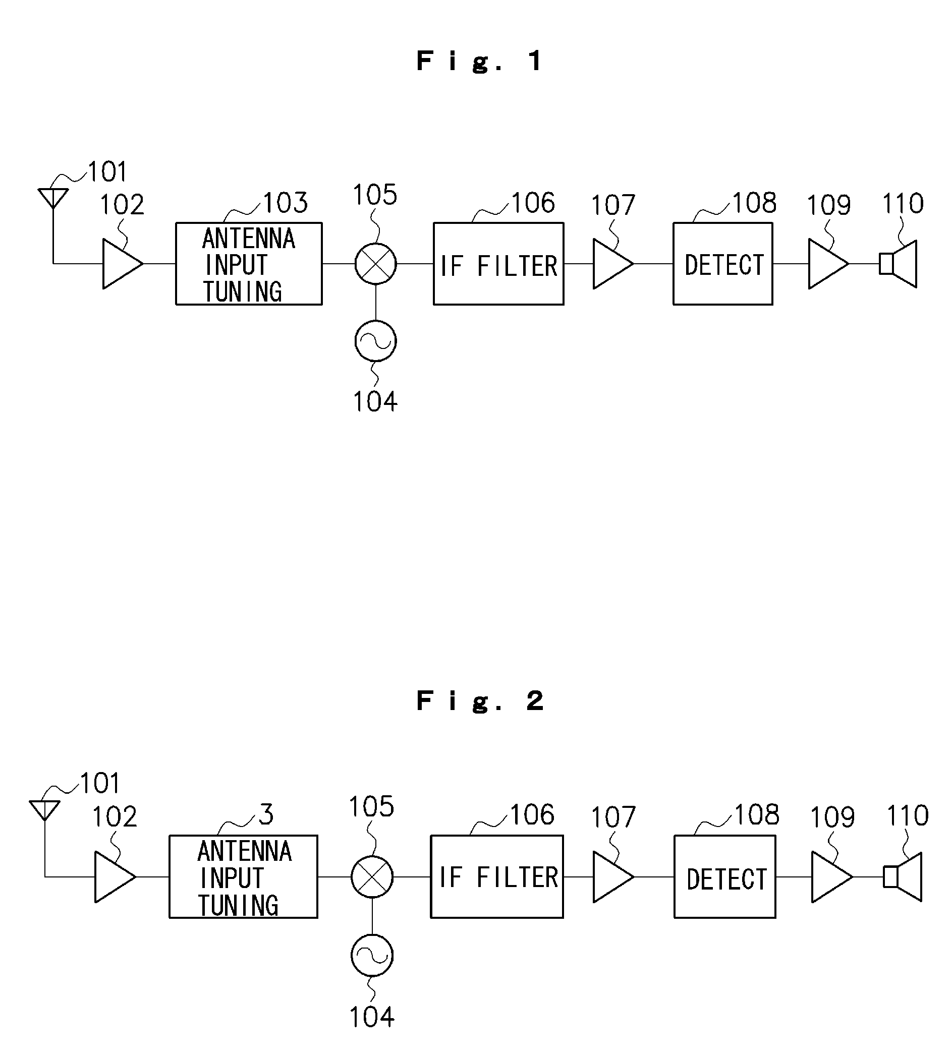
[0026]An embodiment according to the present invention will be described below with reference to the drawings. FIG. 2 is a diagram showing an example of a structure of a radio receiver to which an antenna input tuning circuit according to the present embodiment is applied. In FIG. 2, components having the same functions as those shown in FIG. 1 have the same reference numerals. The respective components shown in FIG. 2 (excluding an antenna 101, an audio amplifying circuit 109 and a speaker 110) are integrated into a single semiconductor chip through a CMOS (Complementary Metal Oxide Semiconductor) process, for example.

[0027]In FIG. 2, an extremely low power radio frequency signal (RF signal) obtained upon receipt of a broadcasting electric wave through the antenna 101 is amplified by a radio frequency amplifying circuit 102 and is then frequency-selected by an antenna input tuning circuit 3 according to the present embodiment in order to enhance a noise factor or to improve a distu...


PUM


Abstract

There are provided a variable tuning filter 11 for selecting any of resistance elements by changing over a switch to cause a tuning frequency fF to be variable, and an oscillating circuit 12 constituted in the same manner as the variable tuning filter 11, and an oscillating frequency fL of the oscillating circuit 12 which is monitored by a frequency counter 13 and a desirable received frequency fr which is preset by a control circuit 14 are compared with each other based on respective frequency count values, and the oscillating frequency fL of the oscillating circuit 12 is varied in such a manner that both of the frequencies are coincident with each other within an allowable error range, and correspondingly, the tuning frequency fF of the variable tuning filter 11 is also varied. Consequently, it is possible to adjust the tuning frequency fF of the variable tuning filter 11 to be coincident with the desirable received frequency fr without using a variable capacitance diode which is hard to integrate or the like.

Description

FIELD OF THE INVENTION[0001]The present invention relates to an antenna input tuning circuit and more particularly to an antenna input tuning circuit for selecting a frequency of a radio frequency signal which is obtained upon receipt of a broadcasting electric wave through an antenna.DESCRIPTION OF THE RELATED ART[0002]In general, a radio receiver is constituted as shown in FIG. 1. More specifically, an extremely low power radio frequency signal (RF signal) obtained upon receipt of a broadcasting electric wave through an antenna 101 is amplified by a radio frequency amplifying circuit 102 and is then frequency-selected by an antenna input tuning circuit 103 in order to enhance a noise factor or to improve a disturbing characteristic. A signal output from the antenna input tuning circuit 103 is mixed with a local oscillating signal generated from a local oscillating circuit 104 and is frequency-converted into an intermediate frequency signal (IF signal) in a mixer circuit 105.[0003]...

Claims


Application Information

Patent Timeline
IPC IPC(8): H04B1/18
CPCH03H11/1252H03H11/1291H03J2200/06H04B1/18H03J2200/18H03L7/08H03L7/0805H03J2200/10
Inventor IKEDA, TAKESHIMIYAGI, HIROSHI
Owner NEURO SOLUTION CORP
Learn More