Laser light irradiation apparatus and laser light irradiation method

a laser light irradiation and laser light technology, applied in the direction of laser details, instruments, optical resonator shape and construction, etc., can solve the problems of causing incident position errors, ejection position errors, and unstable laser light, so as to reduce the error of irradiation position

Inactive Publication Date: 2008-07-24
SEMICON ENERGY LAB CO LTD
View PDF20 Cites 10 Cited by
  • Summary
  • Abstract
  • Description
  • Claims
  • Application Information

AI Technical Summary

Benefits of technology

[0015]In consideration of the above-described problem, it is an object of the present invention to provide a laser light irradiation apparatus and a laser light irradiation method which can reduce errors of an irradiation position of a...

Problems solved by technology

However, laser light is unstable light of which an optical path changes depending on a laser oscillator itself or the state of use environment such as temperature changes.
Therefore, when laser light enters a beam expander optical system, there is a possibility that errors of an incident position at a diffractive optical element can be caused since the laser light does not precisely enter the center of a first lens.
That is, an error of an incident position of the laser light to...

Method used


Image

  • Laser light irradiation apparatus and laser light irradiation method
  • Laser light irradiation apparatus and laser light irradiation method
  • Laser light irradiation apparatus and laser light irradiation method

Examples


embodiment mode 1

[0053]Embodiment Mode 1 will describe one example of a laser light irradiation apparatus and a laser light irradiation method of the present invention with reference to the drawings.

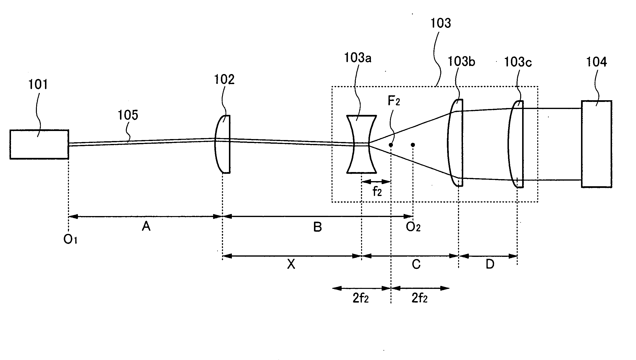
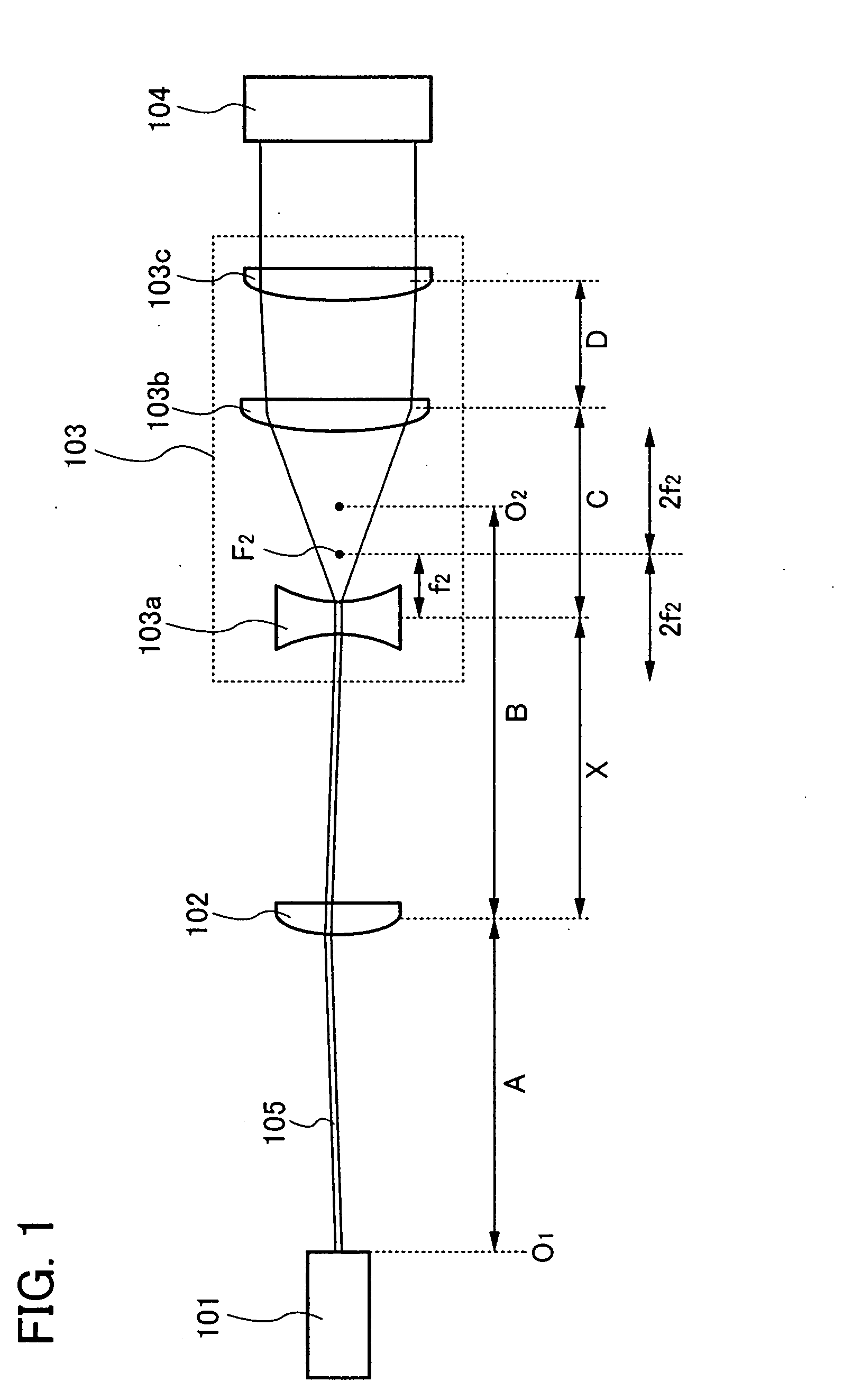
[0054]First, FIG. 1 illustrates a structural example of a laser light irradiation apparatus described in this embodiment mode. The laser irradiation apparatus illustrated in FIG. 1 includes at least a laser oscillator 101, a correction lens 102 which corrects an optical path and a beam expander optical system 103 provided with a zoom function. After laser light 105 oscillated from the laser oscillator 101 is propagated to the beam expander optical system 103 through the correction lens 102 and passes through the beam expander optical system 103 to increase a scale thereof, irradiated object 104 is irradiated with the laser light 105 (see FIG. 1).

[0055]The beam expander optical system of this embodiment mode includes at least three lenses. In the bean expander optical system 103 illustrated in FIG. 1, a f...

embodiment mode 2

[0073]Embodiment Mode 2 will describe a laser light irradiation apparatus and a laser light irradiation method, which are different from those in the above-described embodiment mode, with reference to the drawing. Specifically, the case of using a beam expander optical system including a convex lens as a first lens will be described.

[0074]One structural example of the laser light irradiation apparatus described in this embodiment mode is illustrated in FIG. 3. The laser irradiation apparatus illustrated in FIG. 3 includes at least a laser oscillator 101, a correction lens 102 which corrects an optical path, and a beam expander optical system 203 having a zoom function. Laser light 105 oscillated from the laser oscillator 101 is propagated to the beam expander optical system 103 through the correction lens 102 and passes through the beam expander optical system 203 to increase a scale thereof; therefore an irradiated object 104 is irradiated with the laser light 105 (see FIG. 3)

[0075...

embodiment mode 3

[0089]Embodiment Mode 3 will describe a method for manufacturing a semiconductor device which uses the laser light irradiation apparatus or the laser light irradiation method described in the above-described embodiment modes, with reference to the drawings.

[0090]First, a peeling layer 702 is formed over a surface of a substrate 701, and sequentially, an insulating film 703 to be a base and an amorphous semiconductor film 704 (a film containing amorphous silicon, for example) are formed (see FIG. 6A). It is to be noted that the peeling layer 702, the insulating film 703, and the amorphous semiconductor film 704 can be formed sequentially.

[0091]As the substrate 701, a glass substrate, a quartz substrate, a metal substrate or stainless steel substrate with an insulating film formed on the surface, a plastic substrate having heat resistance against the treatment temperature of this step, or the like is preferably used. In the case of using such a substrate, an area and a shape thereof a...


PUM


Abstract

An object is to provide a laser light irradiation apparatus and a laser light irradiation method which reduce errors of an irradiation position of laser light to an irradiated object and allow irradiation with laser light of any size when the irradiated object is irradiated with the laser light through a beam expander optical system. One feature of a laser light irradiation apparatus of the present invention is to include a laser oscillator; a beam expander optical system having a zoom function; and a correction lens disposed to conjugate the laser oscillator and the beam expander optical system including at least a first lens, a second lens, and a third lens in order in a traveling direction of the laser light, wherein the second lens and the third lens are cooperated with each other in accordance with the magnification of the laser light.

Description

BACKGROUND OF THE INVENTION[0001]1. Field of the Invention[0002]The present invention relates to a laser light irradiation apparatus and a laser light irradiation method, and particularly relates to a laser light irradiation apparatus and a laser light irradiation method using a beam expander optical system.[0003]2. Description of the Related Art[0004]Recently, a technique for manufacturing a thin film transistor (hereinafter referred to as a TFT) over a substrate has been drastically advanced and developed for being applied to an active matrix display device. In particular, a TFT using a polycrystalline semiconductor film has a higher electron field-effect mobility (also referred to as a mobility) than a conventional TFT using an amorphous semiconductor film, so that high-speed operation is possible. Therefore, the control can be carried out by a driver circuit which is formed over the same substrate on which a pixel portion is formed, although the control of a pixel portion has be...

Claims


Application Information

Patent Timeline
IPC IPC(8): G02B27/09
CPCG02B27/0927G02B27/0955G02B27/0944H01S3/10
Inventor TANAKA, KOICHIRO
Owner SEMICON ENERGY LAB CO LTD
Why Eureka
Try Eureka