Multilayer ceramic capacitor

a multi-layer ceramic capacitor and ceramic plate technology, applied in the direction of fixed capacitors, stacked capacitors, fixed capacitor details, etc., can solve the problems of reducing the width direction of the stacked body, the strength of the side margin portion is not sufficient, so as to achieve the effect of preventing water ingress, increasing the strength of the side margin portion, and improving the deflective strength of the multi-layer ceramic capacitor

Active Publication Date: 2017-01-19
MURATA MFG CO LTD
View PDF6 Cites 114 Cited by
  • Summary
  • Abstract
  • Description
  • Claims
  • Application Information

AI Technical Summary

Benefits of technology

[0014]In a multilayer ceramic capacitor according to a preferred embodiment of the present invention, when regions where the first internal electrodes or the second internal electrodes are not present are regarded as the side margin portions in the laminated body as viewed from the laminating direction, the side margin portions have multiple side margin layers, and the content of Si in the side margin layer closest to the internal electrode is lower than that in the side margin layer other than the side margin layer closest to the internal electrode. Thus, the strength of the side margin portions is increased. Thus, the deflecting strength of the multilayer ceramic capacitor is improved. Furthermore, the side margin portions are made less likely to be cracked or chipped, and ingress of water is thus able to be prevented. Thus, insulating properties of the multilayer ceramic capacitor are able to be ensured. As a result, the multilayer ceramic capacitor achieves sufficient reliability.
[0015]According to various preferred embodiments of the present invention, a multilayer ceramic capacitor achieves improved reliability by improving the strength of side margin portions even when the side margin portions have a small dimension in the width direction.

Problems solved by technology

However, the multilayer ceramic capacitor in JP 61-248413 A fails to achieve sufficient strength for the side margin portions, for example, when the thicknesses of the side margin portions, that is, the dimension of the stacked body in the width direction is reduced for the purpose of achieving higher capacitance in a smaller size of multilayer ceramic capacitor.
Thus, the multilayer ceramic capacitor in JP 61-248413 A has the problem of failing to achieve sufficient deflecting strength.
Moreover, the side margin portions are made more likely to be cracked or chipped, and ingress of water is caused from the cracks or chips.
Thus, the multilayer ceramic capacitor in JP 61-248413 A has the problem of decreased insulation properties.

Method used


Image

  • Multilayer ceramic capacitor
  • Multilayer ceramic capacitor
  • Multilayer ceramic capacitor

Examples


example

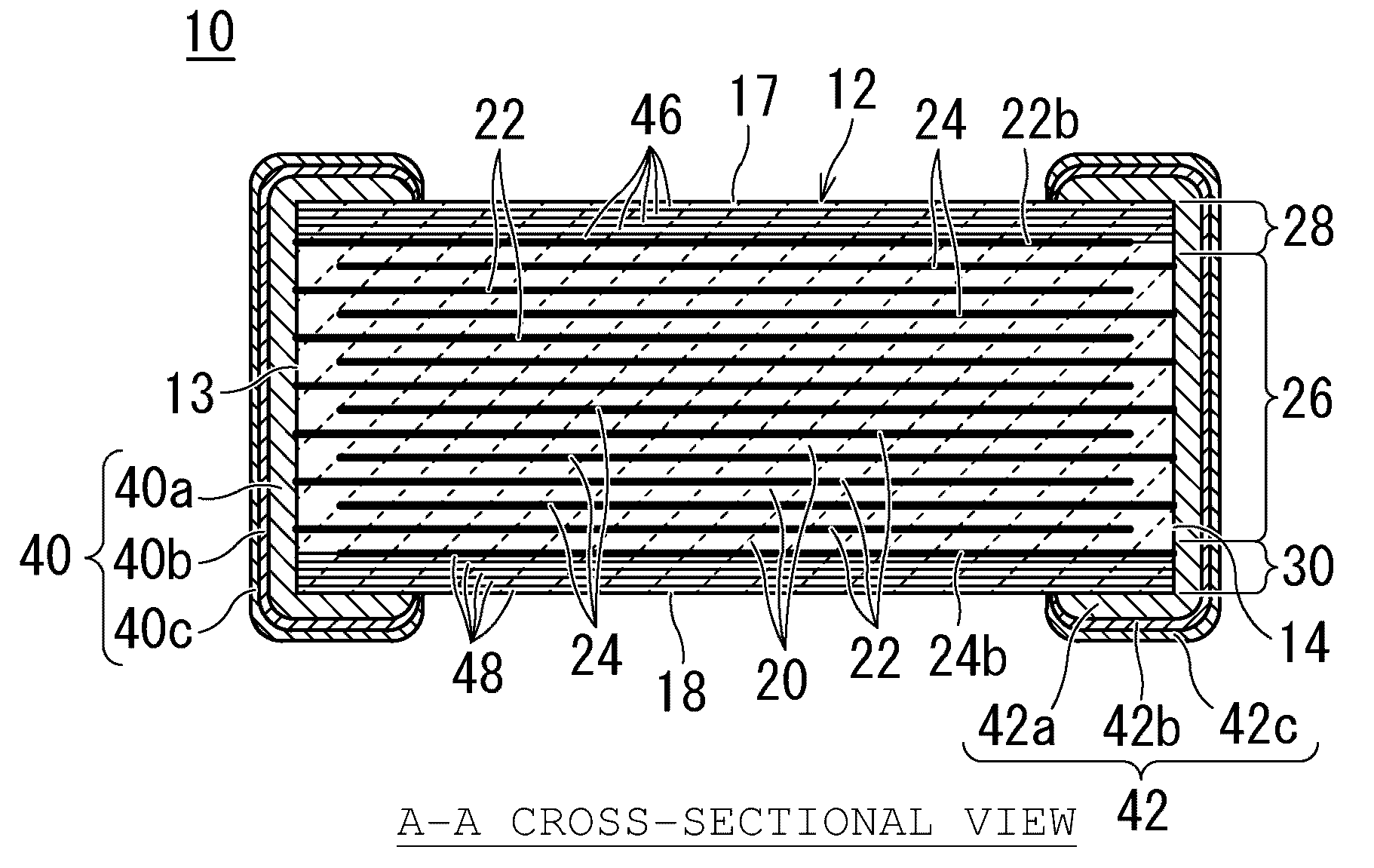
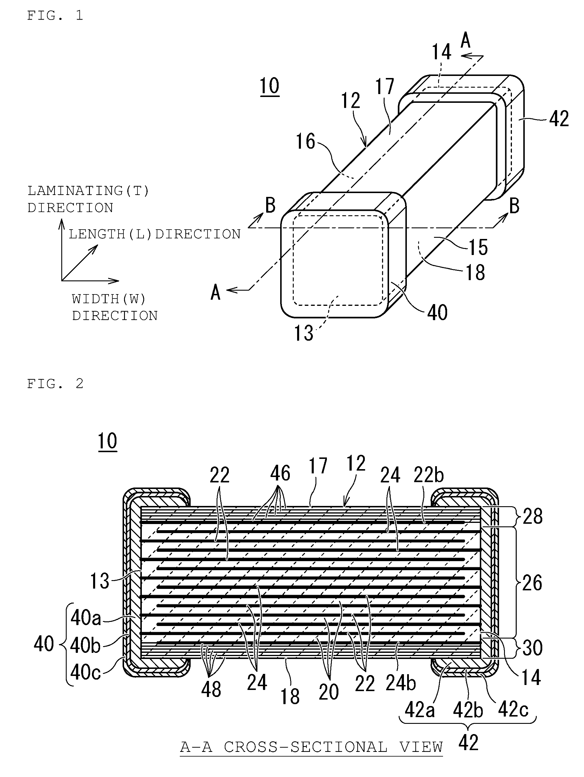
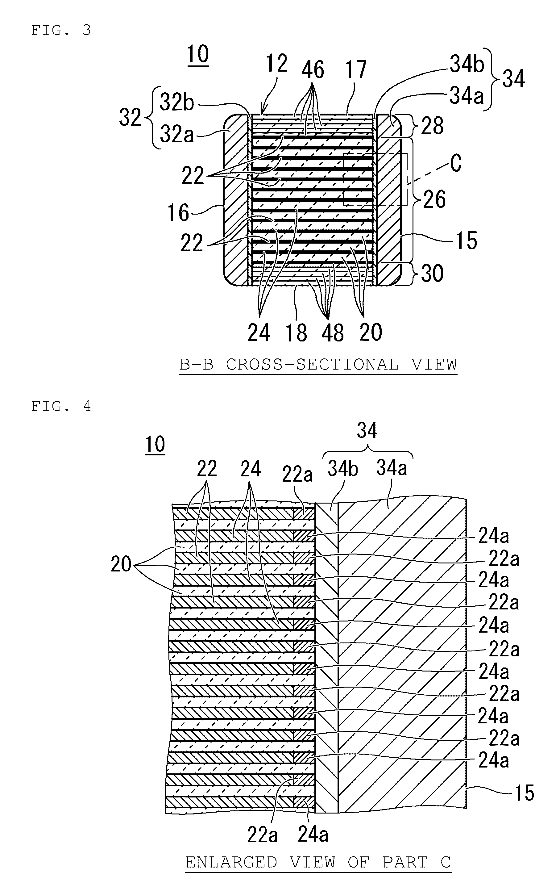
[0097]First, in the example, the sample of the multilayer ceramic capacitor shown in FIG. 1 was produced by the method mentioned above. In this case, the external dimensions of the multilayer ceramic capacitor were made about 1.0 mm in length, about 0.5 mm in width, and about 0.5 mm in height, for example. In the example, prepared was the multilayer ceramic capacitor including side margin portions of two-layer structure composed of an inner layer containing Si at a Si mole number / Ti mole number of about 3.5 with respect to Ti and an outer layer containing Si at a Si mole number / Ti mole number of about 5 with respect to Ti. In addition, the thickness of the side margin portion was made about 20 μm. It is to be noted that for the side margin portion according to the example, the thickness of the outer layer was made about 16 μm, and the thickness of the inner layer was made about 4 μm.


PUM

PropertyMeasurementUnit
widthaaaaaaaaaa
widthaaaaaaaaaa
thicknessaaaaaaaaaa

Abstract

A multilayer ceramic capacitor includes a laminated body and first and second external electrodes respectively on both end surfaces of the laminated body. When regions where first internal electrodes or second internal electrodes are not present are regarded as side margin portions in a cross section of the laminated body as viewed from the laminating direction, the side margin portions include multiple side margin layers, and the content of Si in the side margin layer closest to the internal electrode is lower than that in the side margin layer other than the side margin layer closest to the internal electrode.

Description

CROSS REFERENCE TO RELATED APPLICATIONS[0001]This application claims the benefit of priority to Japanese Patent Application 2015-142975 filed Jul. 17, 2015, the entire contents of which are hereby incorporated by reference.BACKGROUND OF THE INVENTION[0002]1. Field of the Invention[0003]The present invention relates to a multilayer ceramic capacitor.[0004]2. Description of the Related Art[0005]In recent years, multilayer ceramic capacitors have been required which are high in capacitance and small in size. Such multilayer ceramic capacitors each have a laminated body formed in a rectangular or substantially rectangular parallelepiped shape, for example, where dielectric layers for inner layers with internal electrodes printed and the internal electrodes are laminated alternately, and furthermore, ceramic layers for outer layers are laminated on the upper surface and lower surface thereof. Further, the capacitors each have external electrodes formed on both end surfaces of the laminat...

Claims


Application Information

Patent Timeline
Patent Type & Authority Applications(United States)
IPC IPC(8): H01G4/30H01G4/12H01G4/005H01G4/248
CPCH01G4/30H01G4/005H01G4/1218H01G4/248H01G4/012H01G4/1209H01G4/232H01G4/008H01G4/2325H01G4/1227
Inventor TANAKA, HIDEAKIFUKUNAGA, DAIKIMORIYAMA, KOJI
Owner MURATA MFG CO LTD
Why Eureka
Try Eureka