
Method for monitoring the state of the earthing contacts of a contactor controllable by means of an exciter coil

Active Publication Date: 2017-01-19
ROBERT BOSCH GMBH
View PDF3 Cites 0 Cited by
  • Summary
  • Abstract
  • Description
  • Claims
  • Application Information

AI Technical Summary

Benefits of technology

The invention is a method for monitoring the temperature of earthing contacts in electrical devices to prevent thermal failure. The method uses a thermal model to determine the temperature based on the measured voltage and current across the earning contacts. The model takes into account factors like power loss and heat dissipation. The method also includes a correction variable to account for variations in the measured voltage and current. The invention can detect voltage dropping and current flow through the earning contacts to determine the temperature. The method can also determine the temperature of the exciter coil based on the measured voltage and current, and the resistance of the coil. The invention can help prevent thermal failure and reduce the risk of damage to electrical devices.

Problems solved by technology

In so doing, there is the problem that the contactor ages with every switching process, i.e the earthing contacts become more highly resistive.
If a contactor isolates high currents or respectively high currents flow across the earthing contacts of the contactor, a so-called burn-off results, in particular when an electric arc is formed between the earthing contacts.
Because the burn-off leads to a reduction in the contact material of the earthing contacts, said earthing contacts wear with time, which leads to a limited service life of such contactors and makes them more highly resistive.
A common problem here is that an earthing contact once welded or partially welded as a result of an arc formation can loosen again, for example due to vehicle vibrations, and the contactor has then a high contact transition resistance without the monitoring recognizing this fact.
The high transition resistance can then lead to a significant increase in temperature of the earthing contacts when the electric currents are high.
In the case of a current of 400 A, the power loss even amounts to 160 W. The earthing contacts can thus greatly heat up when there is a high electric contact transition resistance and high currents, whereby the risk of a case of thermal failure increases.
A significant disadvantage with this is that the actual condition of the contactor is not taken into account and thus the contactor is generally replaced too early.

Method used


Image

  • Method for monitoring the state of the earthing contacts of a contactor controllable by means of an exciter coil
  • Method for monitoring the state of the earthing contacts of a contactor controllable by means of an exciter coil
  • Method for monitoring the state of the earthing contacts of a contactor controllable by means of an exciter coil

Examples


Embodiment Construction

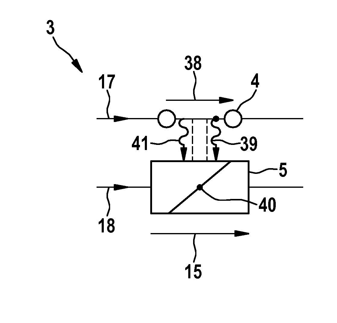
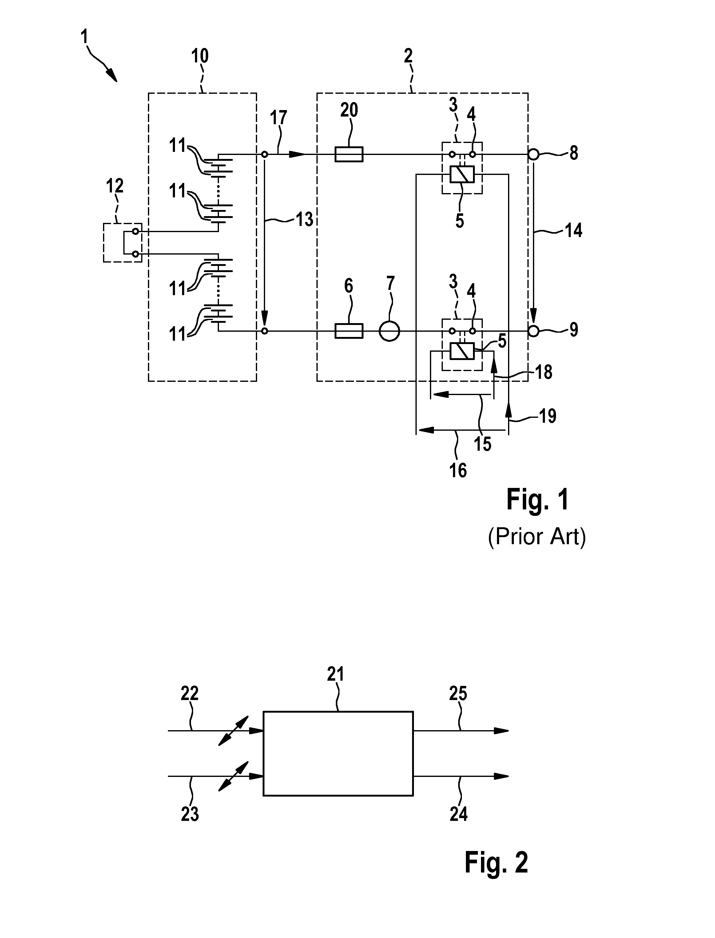
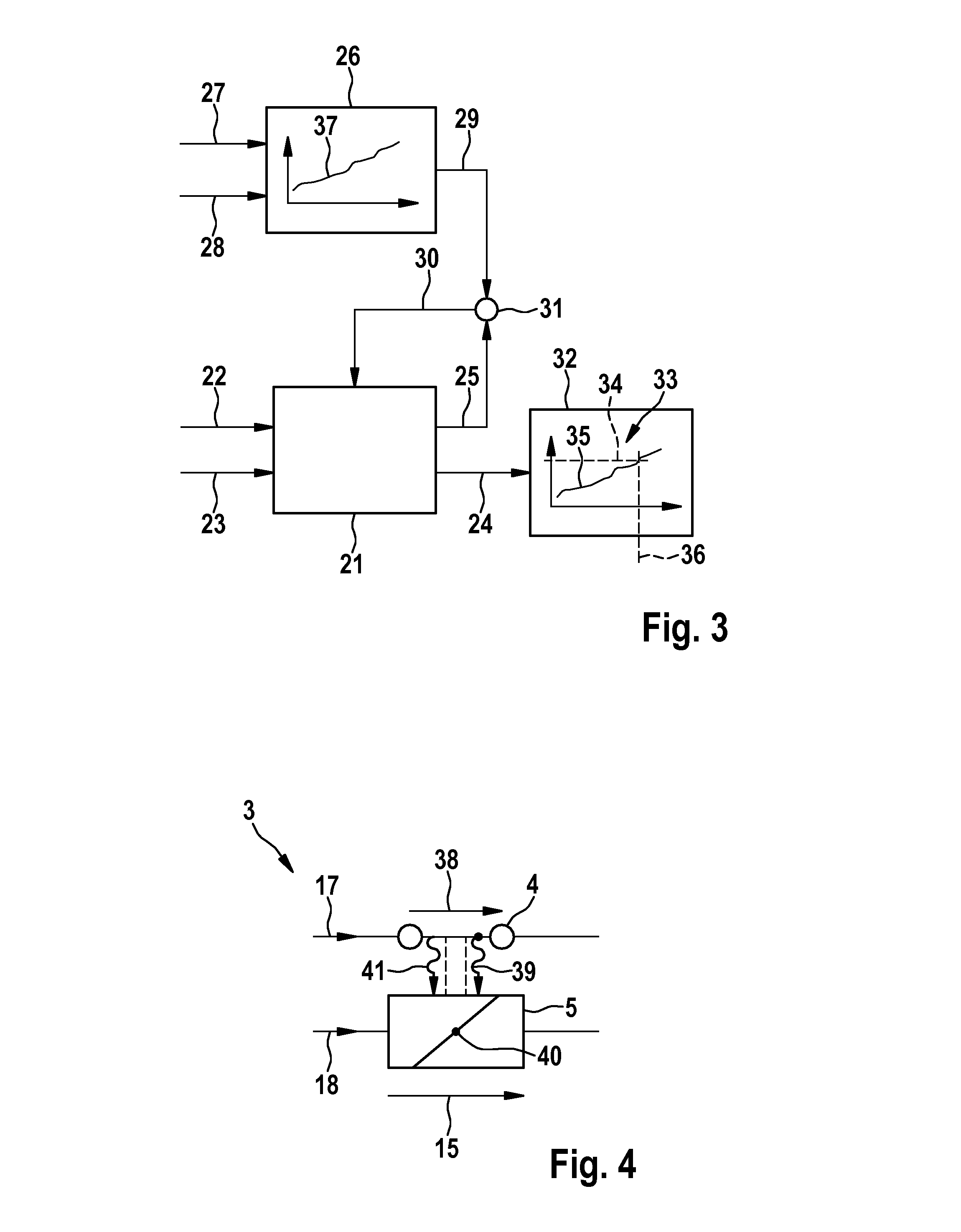
[0026]The battery system 1 depicted in FIG. 1 comprises a traction battery 10 having a plurality of battery cells that are electrically connected to one another. In addition, the traction battery 10 comprises a service plug 12. In order, in case of emergency, to be able to galvanically isolate the traction battery 10 at all of the poles from a consumer device (not explicitly depicted in FIG. 1), in particular a vehicle or a charging device for charging said traction battery 10, the battery system 1 comprises an isolation unit 2 for galvanically isolating said traction battery 10 from the consumer device.

[0027]The isolation unit comprises two contactors 3 controllable in each case by means of an exciter coil 5. The contactors 4 open in the case of a fault and thus galvanically isolate the traction battery 10 from a consumer device connected to said traction battery 10 via the connection terminals 8, 9. Besides the contactors 3, the isolation unit 2 comprises a first current sensor 6,...


PUM


Abstract

The present invention relates to a method for monitoring the state of the earthing contacts of a contactor controlled by an exciter coil, said contactor being operated as part of an isolation unit for galvanically isolating a voltage source from an electric consumer device connected to the voltage source, wherein a first power loss (22), which is transferred via the earthing contacts, and a second power loss (23), which is transferred via the exciter coil, are detected, and the first power loss (22) and the second power loss (23) are fed as input variables to a thermal model (21) of the contactor, the thermal model (21) determines an earthing contact temperature (24) according to at least one of the input variables and provides said contactor temperature as an output variable, and the provided earthing contact temperature (24) is evaluated.

Description

BACKGROUND OF THE INVENTION[0001]The invention relates to a method for monitoring the state of the earthing contacts of a contactor controlled by an exciter coil, said contactor being operated as part of an isolation unit for galvanically isolating a voltage source from an electric consumer device connected to the voltage source.[0002]Contactors controllable by means of an exciter coil are known in various embodiments in the prior art. For example, the German printed publication DE 10 2010 032 456 A1 discloses an electric contactor comprising main and auxiliary contacts as earthing contacts. Such contactors are particularly used in battery systems of at least partially electrically operated vehicles in order if necessary, for example in the case of a fault in the battery of the battery system or a vehicle accident, to galvanically isolate the battery from the vehicle or from a charging device for recharging the battery, i.e from an electric consumer device.[0003]In so doing, there i...

Claims


Application Information

Patent Timeline
IPC IPC(8): H01H47/00B60L3/04G01R21/133B60L3/00H01H47/02G01K7/42
CPCH01H47/002H01H47/02G01K7/427G01R21/133B60L3/0046B60L2240/549H01H2047/025B60L11/1864B60L2240/36B60L2240/547B60L3/04B60L58/21B60L2270/145H01H2047/009H01H2071/044G01R31/3278Y02T10/70
Inventor COIS, OLIVIER
Owner ROBERT BOSCH GMBH
Learn More