Correction method for image forming apparatus

a technology of image forming apparatus and correction method, which is applied in the direction of electrographic process apparatus, instruments, optics, etc., can solve the problems of difficulty in stably performing banding correction, and achieve the effect of satisfying image quality

Active Publication Date: 2017-01-19
CANON KK
View PDF0 Cites 13 Cited by
  • Summary
  • Abstract
  • Description
  • Claims
  • Application Information

AI Technical Summary

Benefits of technology

[0008]The present invention has been made under the above-mentioned circumstances, and it is an object of the present invention to obtain satisfactory image quality by correcting uneven image density of an image, which occurs in a direction corresponding to a rotational direction of a photosensitive member.

Problems solved by technology

Therefore, it is difficult to perform banding correction stably.
Thus, when the scanning line, that is, the image position is deviated from the ideal position in the image area, a problem, e.g., a hue variation occurs, and hence a configuration to move the absolute position of image data is required.

Method used


Image

  • Correction method for image forming apparatus
  • Correction method for image forming apparatus
  • Correction method for image forming apparatus

Examples


embodiment

Overall Configuration of Image Forming Apparatus

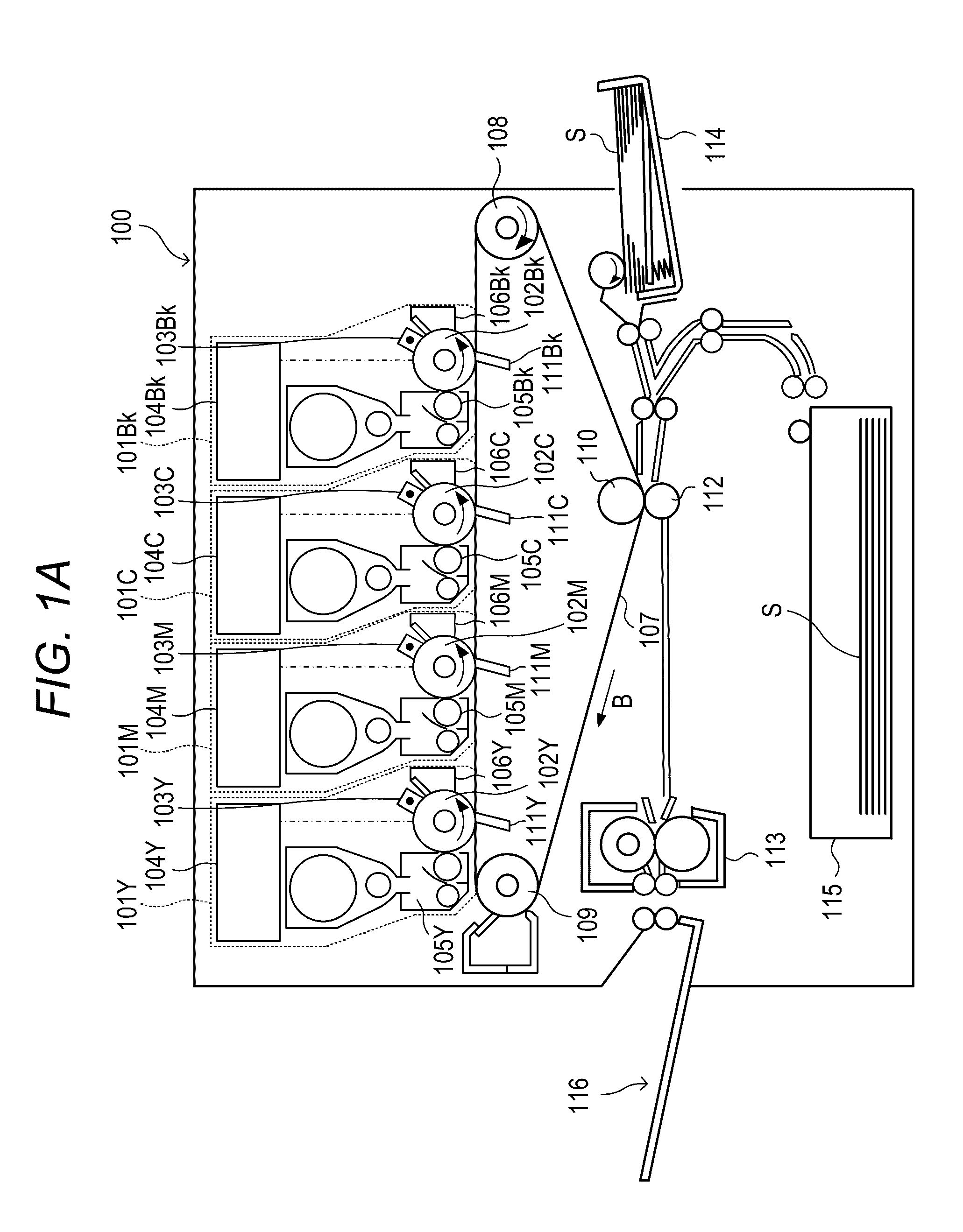
[0036]FIG. 1A is a schematic cross-sectional view of a digital full-color printer (color image forming apparatus) configured to perform image formation by using toners of a plurality of colors. An image forming apparatus 100 according to an embodiment will be described with reference to FIG. 1A. The image forming apparatus 100 includes four image forming portions (image forming units) 101Y, 101M, 101C, and 101Bk (broken line portions) respectively configured to form images of different colors. The image forming portions 101Y, 101M, 101C, and 101Bk form images by using toners of yellow, magenta, cyan, and black, respectively. Reference symbols Y, M, C, and Bk denote yellow, magenta, cyan, and black, respectively, and suffixes Y, M, C, and Bk are omitted in the description below unless a particular color is described.

[0037]The image forming portions 101 each include a photosensitive drum 102, being a photosensitive member. A charging dev...


PUM


Abstract

A correction method for an image forming apparatus including a light source including a plurality of light emitting points, a photosensitive member configured to rotate in a first direction so that a latent image is formed thereon with light beams emitted from the light source, and a deflecting unit configured to deflect the light beams emitted from the light source in a second direction orthogonal to the first direction to form scanning lines, the correction method including a correction step of correcting sparseness and denseness of density in the first direction caused by deviation of the scanning lines in the first direction by moving a predetermined pixel in the first direction in accordance with the deviation of the scanning lines and causing a pixel value of the predetermined pixel to be output in accordance with a movement of the predetermined pixel.

Description

BACKGROUND OF THE INVENTION[0001]Field of the Invention[0002]The present invention relates to a correction method for an image forming apparatus, for correcting distortion and uneven image density of an image during image formation of a two-dimensional image by the image forming apparatus, e.g., a digital copying machine, a multifunctional peripheral, or a laser printer.[0003]Description of the Related Art[0004]In electrophotographic image forming apparatus such as a laser printer and a copying machine, there has been generally known a configuration to form a latent image on a photosensitive member with use of a light scanning device configured to perform scanning with a laser beam. In the light scanning device of a laser scanning type, a laser beam collimated with use of a collimator lens is deflected by a rotary polygon mirror, and the deflected laser beam is formed into an image on a photosensitive member with use of an elongated fθ lens. Further, there is known multibeam scannin...

Claims


Application Information

Patent Timeline
Patent Type & Authority Applications(United States)
IPC IPC(8): H04N1/405H04N1/113G03G15/043H04N1/06
CPCH04N1/4052H04N1/06H04N2201/0094G03G15/043H04N1/113H04N1/506
Inventor FURUTA, YASUTOMOHORIUCHI, IZURUARAKI, RYUICHI
Owner CANON KK
Why Eureka
Try Eureka