Method and apparatus for coupling anatomical features

Active Publication Date: 2017-01-26
BIOMET SPORTS MEDICINE
View PDF6 Cites 73 Cited by
  • Summary
  • Abstract
  • Description
  • Claims
  • Application Information

AI Technical Summary

Benefits of technology

[0005]To improve on these uses, sutures having a single preformed loop have been provided. FIG. 1 represents a prior art suture construction. As shown, one end of the suture is passed through a passage defined in the suture itself. The application of tension to

Problems solved by technology

For example, the procedure of tying knots may be very time consuming, thereby increasing the cost of the procedure and limiting the capacity of the surgeon.
Furthermore, the strength of the repair may be limited by the streng

Method used


Image

  • Method and apparatus for coupling anatomical features
  • Method and apparatus for coupling anatomical features
  • Method and apparatus for coupling anatomical features

Examples


Embodiment Construction

[0031]The following description is merely exemplary in nature and is not intended to limit the present disclosure, application, or uses. It should be understood that throughout the drawings, corresponding reference numerals indicate like or corresponding parts and features.

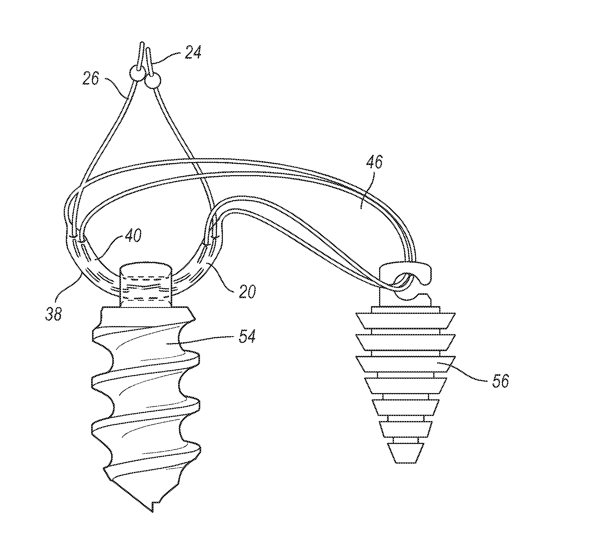
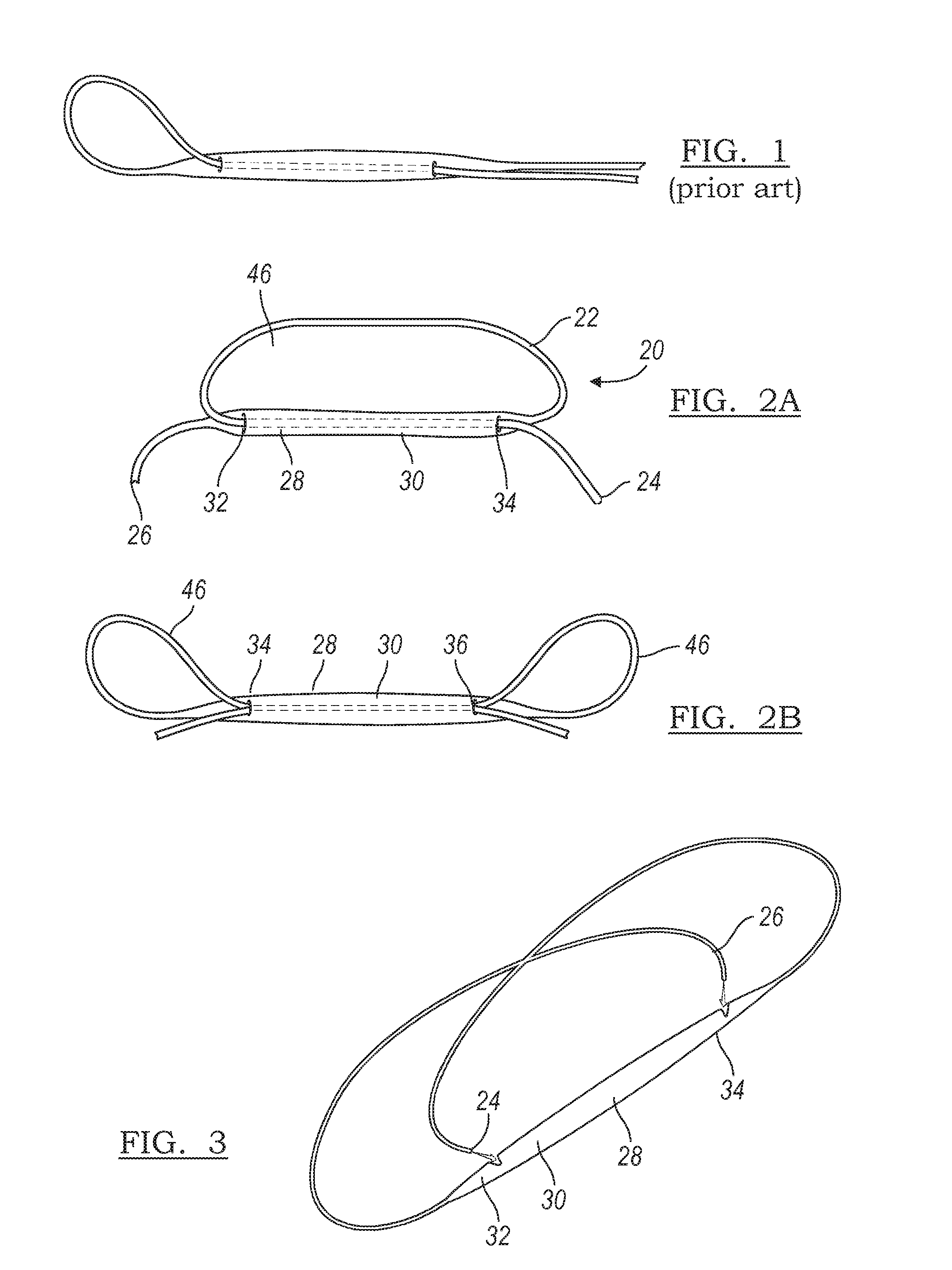
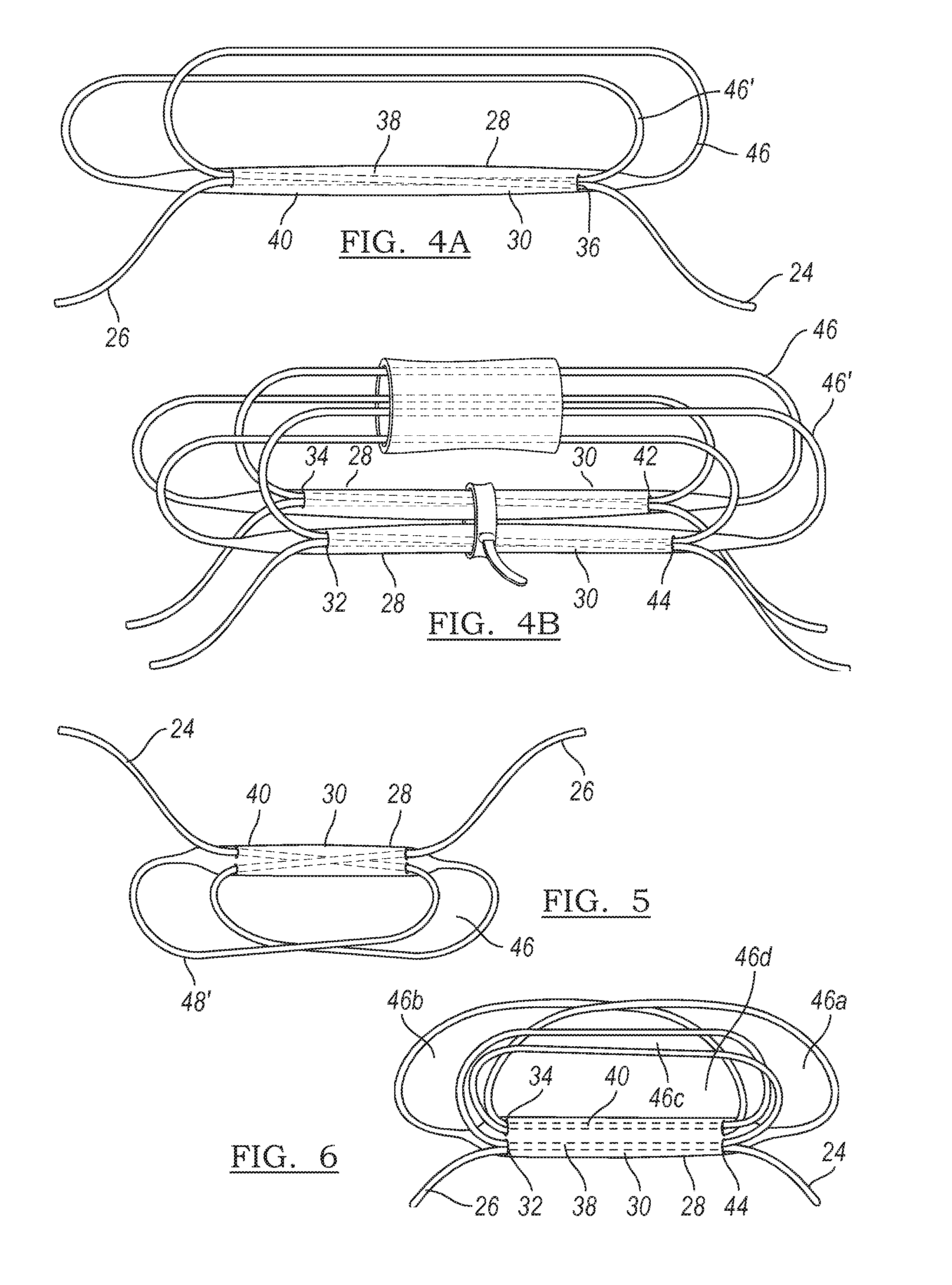
[0032]FIG. 2A represents a suture construction 20 according to the present teachings. Shown is a suture 22 having a first end 24 and a second end 26. The suture 22 is formed of a braided body 28 that defines a longitudinally formed hollow passage 30 therein. First and second apertures 32 and 34 are defined in the braided body 28 at first and second locations of the longitudinally formed passage 30.

[0033]Briefly referring to FIG. 3, a first end 24 of the suture 22 is passed through the first aperture 32 and through longitudinal passage 30 formed by a passage portion and out the second aperture 34. The second end 26 is passed through the second aperture 34, through the passage 30 and out the first aperture 32. This ...


PUM


Abstract

A method of coupling a first portion of an anatomy to a second portion of the anatomy includes coupling first and second bones of the anatomy with a bone-tendon-bone implant. The bone-tendon-bone implant has a first bone end, a second bone end and a replacement tendon between the first and second bone ends. The first and second bone ends are positioned in corresponding first and second bores of the first and second bones. The first bone end is secured to the first bone with a first bone anchor. A second anchor coupled to the bone-tendon-bone implant is passed through and outside the second bore. The second anchor is coupled to an adjustable suture construct having two adjustable suture loops. Tensioning at least one of first and second ends of the adjustable suture construct tensions the replacement tendon and positions the first bone relative to the second bone.

Description

CROSS-REFERENCE TO RELATED APPLICATIONS[0001]This application is a divisional of U.S. patent application Ser. No. 13 / 412,116 filed on Mar. 5, 2012, which is a divisional of U.S. application Ser. No. 12 / 196,407 filed on Aug. 22, 2008, now U.S. Pat. No. 8,137,382 issued on March 20, 2012, which is a continuation-in-part application of: (1.) U.S. patent application Ser. No. 11 / 541,506 filed on Sep. 29, 2006, now U.S. Pat. No. 7,601,165 issued Oct. 13, 2009; (2.) U.S. patent application Ser. No. 12 / 014,399 filed on Jan. 15, 2008, now U.S. Pat. No. 7,909,851 issued Mar. 22, 2011; (3.) U.S. patent application Ser. No. 12 / 014,340 filed on Jan. 15, 2008, now U.S. Pat. No. 7,905,904 issued Mar. 15, 2011; (4.) U.S. patent application Ser. No. 11 / 935,681 filed on Nov. 6, 2007, now U.S. Pat. No. 7,905,903 issued Mar. 15, 2011; (5.) U.S. patent application Ser. No. 11 / 869,440 filed on Oct. 9, 2007, now U.S. Pat. No. 7,857,830 issued Dec. 28, 2010; (6.) U.S. patent application Ser. No. 11 / 784,821...

Claims


Application Information

Patent Timeline
IPC IPC(8): A61B17/04A61F2/08A61B17/06
CPCA61B17/0401A61B17/0487A61B17/06166A61F2/0811A61B2017/0412A61F2002/0882A61B2017/044A61B2017/0464A61B2017/0496A61F2002/087A61B2017/0414A61B17/0469A61B2017/0404A61B2017/0417A61B2017/0419A61B2017/0641A61F2002/0829A61F2002/0852A61F2002/0864A61F2002/0888A61B2017/0409A61B2017/0445A61B2017/0448A61B2017/045A61B2017/0458A61B2017/0475A61B2017/06185A61F2/08Y10T29/49826A61B17/04
Inventor DENHAM, GREGORY J.STONE, KEVIN T.
Owner BIOMET SPORTS MEDICINE
Why Eureka
Try Eureka