A nacelle for a wind turbine generator including lifting apparatus

a technology nacelles, which is applied in the direction of wind turbine generators, motors, cranes, etc., can solve the problems of increasing wear on the components of cranes where the boom is located, and achieve the effect of preventing overloading of the support structure and/or inappropriate loading of the nacell

Active Publication Date: 2017-01-26
VESTAS WIND SYST AS
View PDF4 Cites 17 Cited by
  • Summary
  • Abstract
  • Description
  • Claims
  • Application Information

AI Technical Summary

Benefits of technology

[0006]Beneficially, therefore, the invention provides a lifting apparatus in which the boom is supported against a boom rest and thereby inhibited from oscillation motion of the boom. As mentioned above, wind turbine generators generate significant dynamic loads in use which can influence strongly the cantilevered arrangement of a boom with respect to its base, particularly if frequencies of the vibrations coincide with the natural frequency of the boom crane. This can increase wear on the component parts of the crane where the boom is mounted. Holding the boom of the crane against a fixed support reduces the dynamic loads on the crane when in the stowed condition thereby improving the reliability of the crane.
[0007]In principle, the boom may be held against a support at any point along its length which would be such as to inhibit unwanted oscillations of the boom. However, in one configuration the support structure is positioned such that a free end of the boom rests against it, which provides the most effective damping of dynamic loads through the crane.
[0009]In one embodiment, the crane is configured to be able to hoist payloads when in the stowed condition. In effect, therefore, the crane may be converted to a static hoist when in the stowed condition. One benefit of this is that the crane can be operated when in the stowed condition by personnel who may not otherwise be suitably qualified to operate the crane when in the deployed condition. Optionally, the crane's azimuth and elevation drives may be disabled in a stowed condition thereof while the principal winch may remain enabled for use in said stowed condition. A further benefit from operating the crane in its stowed configuration arises as a result of the crane being in a predetermined position with its lifting line in a known reference position for use. Operation of the crane's principal winch with its lifting line in a reference position removes the need for a skilled or certified crane operator to position the crane for use and ensured that use of the crane in its stowed position is restricted to hoisting operations, i.e. raising and lowering loads, at a given vertical location. In effect, in embodiments, the nacelle crane may be used in its stowed position as a simple hoist in particular for hoisting loads through a hatch in the nacelle floor or for hoisting loads in relation to a particular location or component inside the nacelle.
[0012]The support structure does not have to form part of the crane and, as such, may be external to the crane. For example, the support structure for the boom may be provided by an internal frame structure of the nacelle. As an alternative, the support structure may be mounted directly to or between one or more walls of the nacelle. Providing the support structure as part of the internal frame structure of the nacelle provides the most effective route to distribute the loads from the boom into the main tower structure.
[0015]In a further optional embodiment, there may be provided a pressure gauge device configured to generate a signal indicative of the pressure applied to the support structure by the boom. The pressure gauge device may in particular be configured to generate an alarm signal if the pressure applied to the support structure by the boom exceeds a predetermined threshold. Accordingly, it can be determined and optionally indicated to an operator, how much load is applied to the support structure. In addition, it can be indicated to an operator by way of an alarm or warning signal, if a load limit on the support structure is reached or exceeded. A load limit may be predetermined and entered into a control system of the nacelle or crane. The provision of a pressure gauge device may thereby prevent overloading of the support structure and / or inappropriate loading of the nacelle. In embodiments, a pressure sensor of the pressure gauge device may be provided at the support structure in particular at a support surface thereof. Alternatively, a pressure sensor of the pressure gauge device may be provided at the rest member.
[0016]In one embodiment, the crane is mounted to a housing for a rotating component of the nacelle, such as a low speed shaft including main shaft bearings, gearbox and the like. Such a housing is large and stable and provides a secure mounting point for the crane.

Problems solved by technology

This can increase wear on the component parts of the crane where the boom is mounted.

Method used


Image

  • A nacelle for a wind turbine generator including lifting apparatus
  • A nacelle for a wind turbine generator including lifting apparatus
  • A nacelle for a wind turbine generator including lifting apparatus

Examples


Embodiment Construction

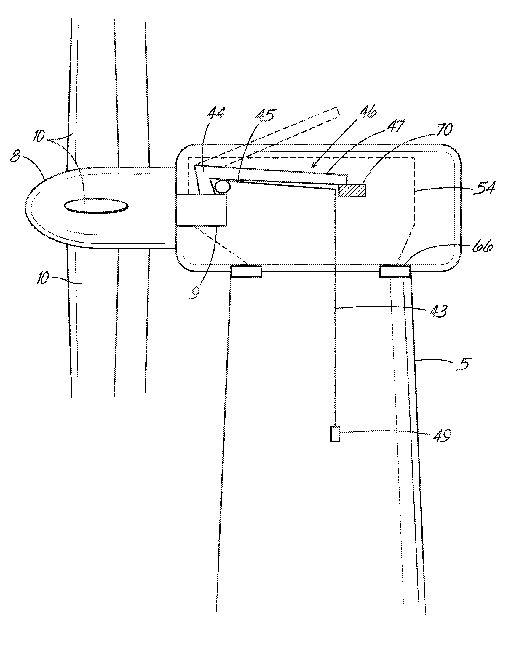
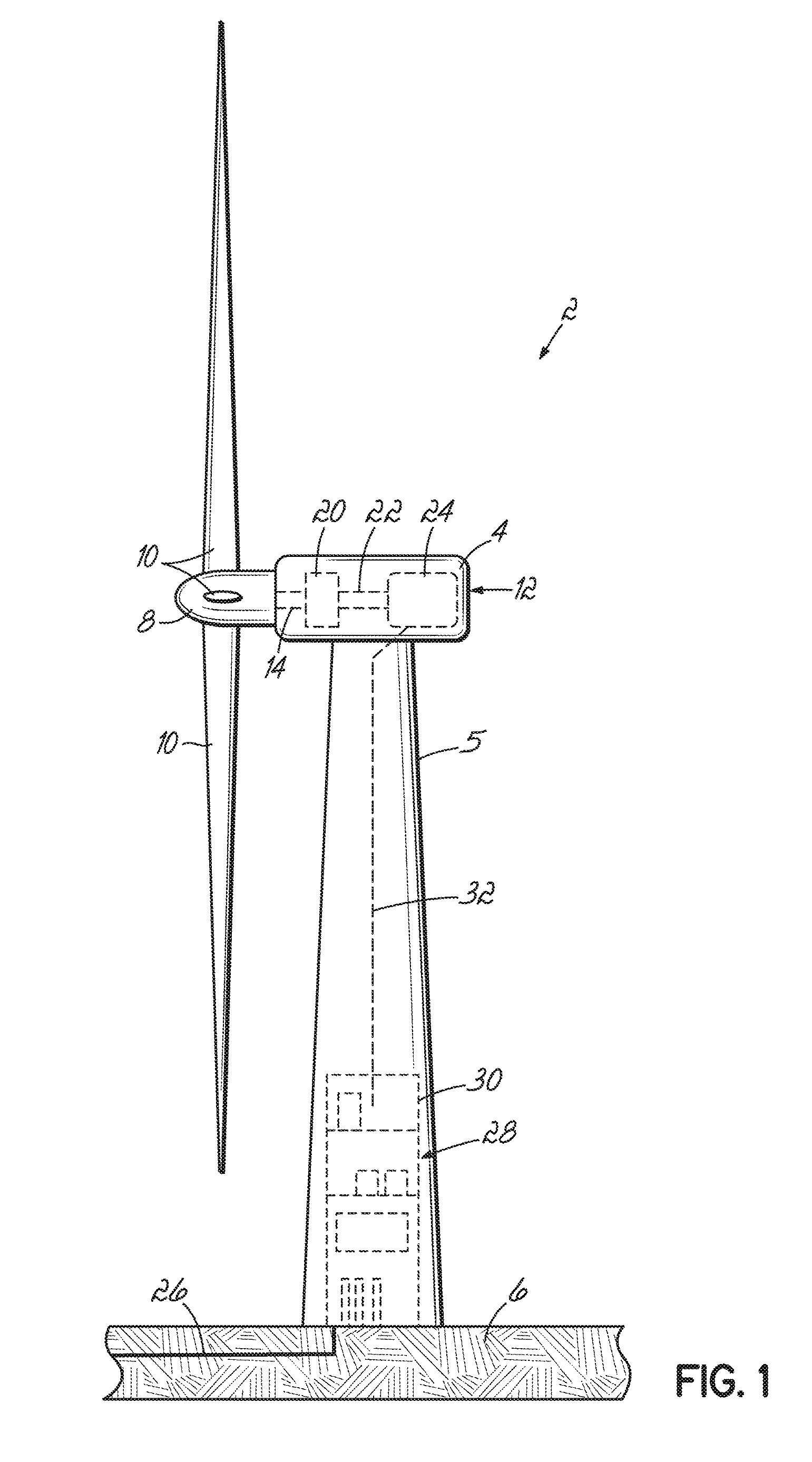
[0029]With reference to FIG. 1, a wind turbine 2 of the horizontal-axis type (HAWT) comprises a nacelle 4 mounted on top of a tower 5 which is itself mounted on a foundation or footing 6. The nacelle 4 includes a hub 8 at its front end which carries a set of rotor blades 10. Three rotor blades 10 are shown in this embodiment, as is common in large utility-scale generators, although the skilled person will appreciated that other numbers of blades are acceptable.

[0030]At this point it should be noted that FIG. 1 is for illustrative purposes only, so it is not to scale and is not intended to be a realistic representation of a wind turbine generator. Also it is to be noted that other tower constructions are known, for example towers defined by structural lattice framework.

[0031]To enable energy to be recovered from the wind-driven rotating blades 10, the nacelle 4 houses a generator set 12, depicted here in dashed lines, that is driven by the hub 8 through a low speed drive shaft 14. Th...


PUM


Abstract

A nacelle for a wind turbine generator comprises a crane articulated on a base fixed to said nacelle. The crane includes a cantilevered telescopic boom, a principal winch with a lifting line and respective azimuth and elevation drive units for moving said boom in azimuth and in elevation relative to said nacelle. The crane has a deployed condition in which said boom is moveable in azimuth and in elevation and a stowed condition. The nacelle comprises a support structure against which said boom is brought to rest in said stowed condition thereof and wherein when in said stowed condition said boom is located into a predetermined position at which it is held to rest at a point along its length against said support structure and wherein said lifting line is in a reference position in relation to said nacelle when said crane is in its stowed condition. A method for operating a crane in a nacelle comprising operating said crane as a static hoist using a principal winch of said crane when in said stowed condition of said crane.

Description

TECHNICAL FIELD[0001]The invention relates to lifting apparatus used in wind turbine generators, particularly nacelles of wind turbine generators.BACKGROUND[0002]Large, utility-scale horizontal-axis wind turbine generators (HAWTs) typically comprise a set of rotor blades mounted to a supporting structure which usually takes the form of a tubular tower. In such HAWTs, the generating components including the generator, gearbox, drive train and brake assembly are located at the top of a tower in a nacelle behind the hub of the rotor blades.[0003]It is known to install lifting apparatus within a nacelle in order to help personnel install heavy components. For example, WO2012 / 107049A1 describes a boom crane that is mounted within a nacelle of a HAWT, wherein the boom is movable in elevation and in azimuth in relation to the nacelle. In a stowed position, the boom crane lies inside the nacelle and is covered by a roof. However, the boom crane can be moved to a deployed condition in which ...

Claims


Application Information

Patent Timeline
Patent Type & Authority Applications(United States)
IPC IPC(8): F03D1/00B66C13/16F03D80/80B66C23/18
CPCF03D1/003B66C23/18B66C13/16F05B2220/7064F05B2240/916F05B2240/14F03D80/88F03D80/50F05B2230/61Y02E10/72Y02E10/728Y02P70/50
Inventor THERKILDSEN, CLAUS HALD
Owner VESTAS WIND SYST AS
Why Eureka
Try Eureka