Slim vapor chamber

a vapor chamber and thin technology, applied in the direction of reinforcement means, lighting and heating apparatus, laminated elements, etc., can solve the problems of reducing the performance or lifetime of products, generating a lot of heat, and components of electronic products, so as to improve the heat conducting speed between the two plates, enhance the heat conducting ability, and the effect of thin siz

Active Publication Date: 2017-01-26
DELTA ELECTRONICS INC
View PDF13 Cites 32 Cited by
  • Summary
  • Abstract
  • Description
  • Claims
  • Application Information

AI Technical Summary

Benefits of technology

[0020]As mentioned above, the slim vapor chamber of the invention has a first plate and a second plate, and a side of the first plate facing the second plate and / or a side of the second plate facing the first plate is formed with a plurality of supporting structures, which include a plurality of supporting pillars and a plurality of supporting plates, by an etching process. Accordingly, the flowing speed of the evaporated working fluid can be increased, so that the heat conducting speed between the two plates can be improved so as to enhance the heat conducting ability. Therefore, the vapor chamber can have a thinner size and a good heat conducting efficiency, thereby providing a better heat conducting ability to the electronic product.

Problems solved by technology

However, when the high performance electronic product is operating, a lot of heat will be generated.
If the heat conducting component and / or the heat-dissipating component is not upgraded, the internal components of the electronic products can be damaged by the generated heat, thereby decreasing the performance or lifetime of the products.
This smaller internal space will decrease the flowing speed of the vapor, thereby reducing the heat conducting ability.
This is an important issue for developing the thinner vapor chamber.
However, the placement and positioning of the supporting pillars are difficult.
In practice, the supporting pillars may be misaligned in the assembling process, which will affect the flowing the vapor and thus decrease the performance of the vapor chamber.
In addition, the flow of the vapor is a kind of non-directional (the flowing direction of the vapor is not consistent), so the temperature difference between the heat and cold ends of the vapor chamber is obvious.
Accordingly, the vapor flow cannot be properly guided to improve the heat conducting efficiency as the vapor chamber is thinner.

Method used


Image

  • Slim vapor chamber
  • Slim vapor chamber
  • Slim vapor chamber

Examples


Embodiment Construction

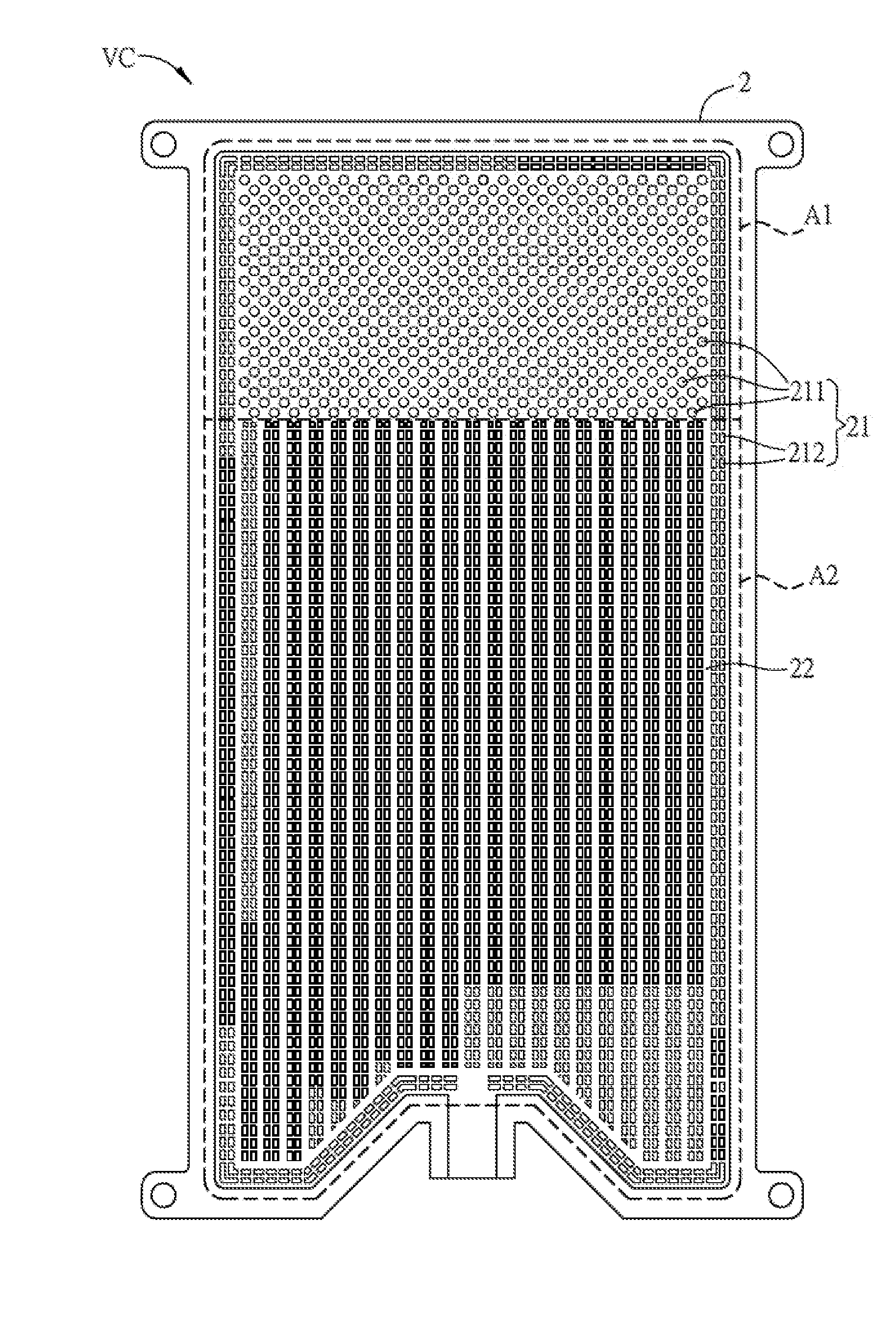
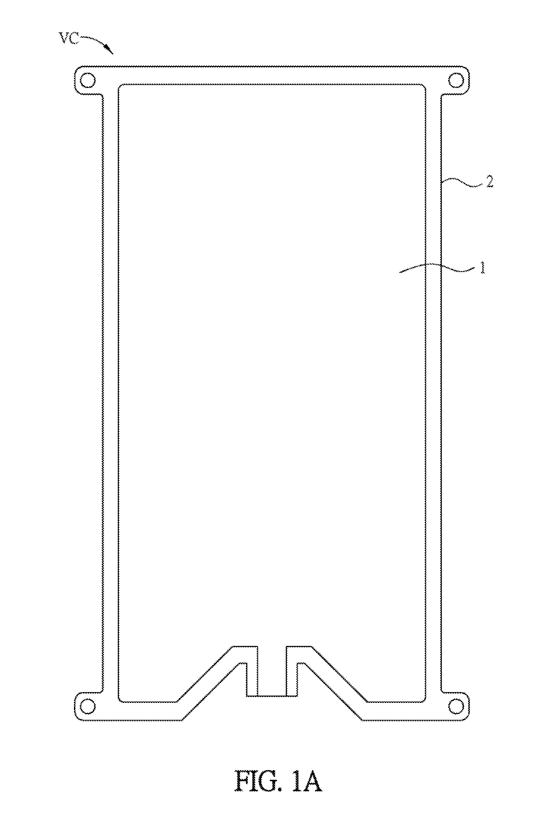
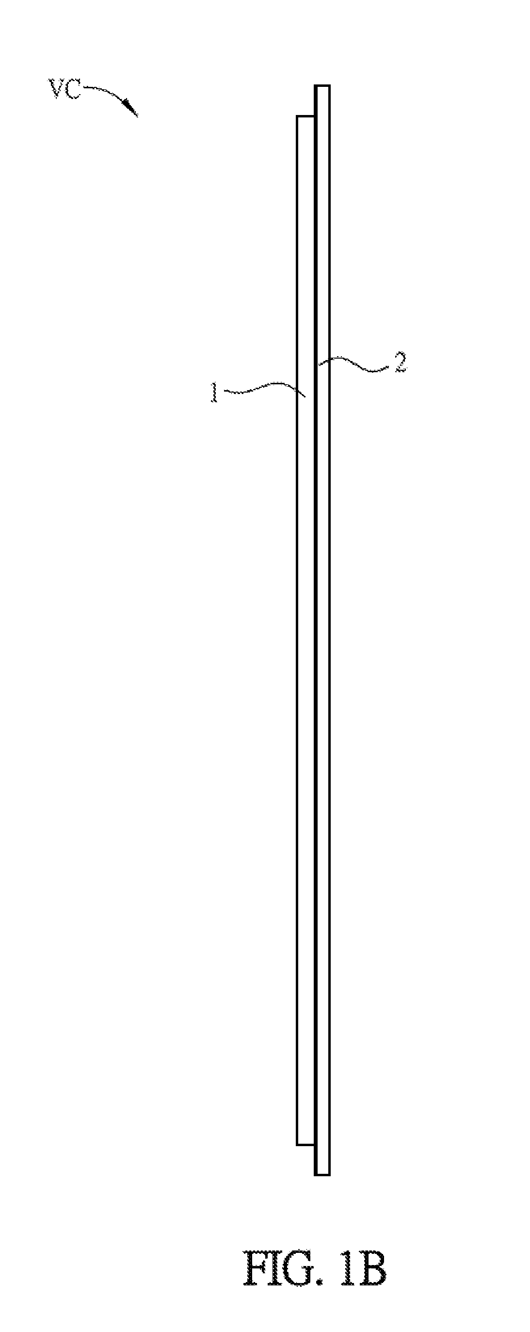
[0034]The embodiments of the invention will be apparent from the following detailed description, which proceeds with reference to the accompanying drawings, wherein the same references relate to the same elements. Moreover, the drawings of all implementation are schematic, and they do not mean the actual size and proportion. The terms of direction recited in the disclosure, for example up, down, left, right, front, or rear, only define the directions according to the accompanying drawings for the convenience of explanation but not for limitation. The names of elements and the wording recited in the disclosure all have ordinary meanings in the art unless otherwise stated. Therefore, a person skilled in the art can unambiguously understand their meanings. In the drawings, the sizes of the arrows represent the flowing speeds of the working fluid (or vapor) in the chamber, and the directions of the arrows represent the flowing direction of the working fluid (or vapor) in the chamber.

[00...


PUM


Abstract

A slim vapor chamber includes a first plate, a second plate and a capillary structure. The periphery of the second plate is connected with that of the first plate to form a chamber. The capillary structure is disposed in the chamber. At least one of a side of the first plate facing the second plate and a side of the second plate facing the first plate is formed with a plurality of supporting structures, which include a plurality of supporting pillars and a plurality of supporting plates, by an etching process.

Description

CROSS REFERENCE TO RELATED APPLICATIONS[0001]This application claims the priority benefits of U.S. provisional application Ser. No. 62 / 194,431, filed on Jul. 20, 2015 and under 35 U.S.C. §119(a) on Patent Application No(s). 201610560393.0 filed in People's Republic of China on Jul. 15, 2016. The entirety of the above-mentioned patent applications are hereby incorporated by references herein and made a part of specification.BACKGROUND OF THE INVENTION[0002]Field of Invention[0003]The present invention relates to a heat conductive device, and in particular, to a slim vapor chamber.[0004]Related Art[0005]As the progress of technology, the electronic products are developed toward the features of portable, light weight, 4K resolution, 4G transmission and high attachment function. However, when the high performance electronic product is operating, a lot of heat will be generated. If the heat conducting component and / or the heat-dissipating component is not upgraded, the internal component...

Claims


Application Information

Patent Timeline
Patent Type & Authority Applications(United States)
IPC IPC(8): F28D15/04F28F13/06F28F3/00
CPCF28D15/046F28F3/00F28D2021/0028F28F2255/18F28F2225/04F28F13/06F28D15/0233F28F3/022
Inventor HUANG, SHIH-LINWU, TING-YUANCHEN, CHIU-KUNGCHIU, CHUN-LUNG
Owner DELTA ELECTRONICS INC
Why Eureka
Try Eureka