Modular intelligent transportation system

Inactive Publication Date: 2017-01-26
THE WILFRED J AND LOUISETTE G LAGASSEY IRREVOCABLE TRUST ROGER J MORGAN TRUSTEE
View PDF21 Cites 34 Cited by
  • Summary
  • Abstract
  • Description
  • Claims
  • Application Information

AI Technical Summary

Benefits of technology

[0127]Known and existing systems and services may readily lend themselves for use with the instant invention, provide a more economical solution for the agency deploying the system, and can use excess capacity and provide additional revenue opportunities for the operators of these services, although it may be desirable to provide operators as such facilities with specialized training. However, there are instances where establishing an independent service or integrating the service into existing dispatching facilities of the local authorities might be the preferred solution.
[0128]In the preferred embodiment, when the transceiver has established a connection with the remote location (“the Monitoring Center”), the control unit initially transmits the location and at least one still image or live video image of the

Problems solved by technology

For example, sensors, controls and communicati

Method used


Image

  • Modular intelligent transportation system
  • Modular intelligent transportation system
  • Modular intelligent transportation system

Examples


Example

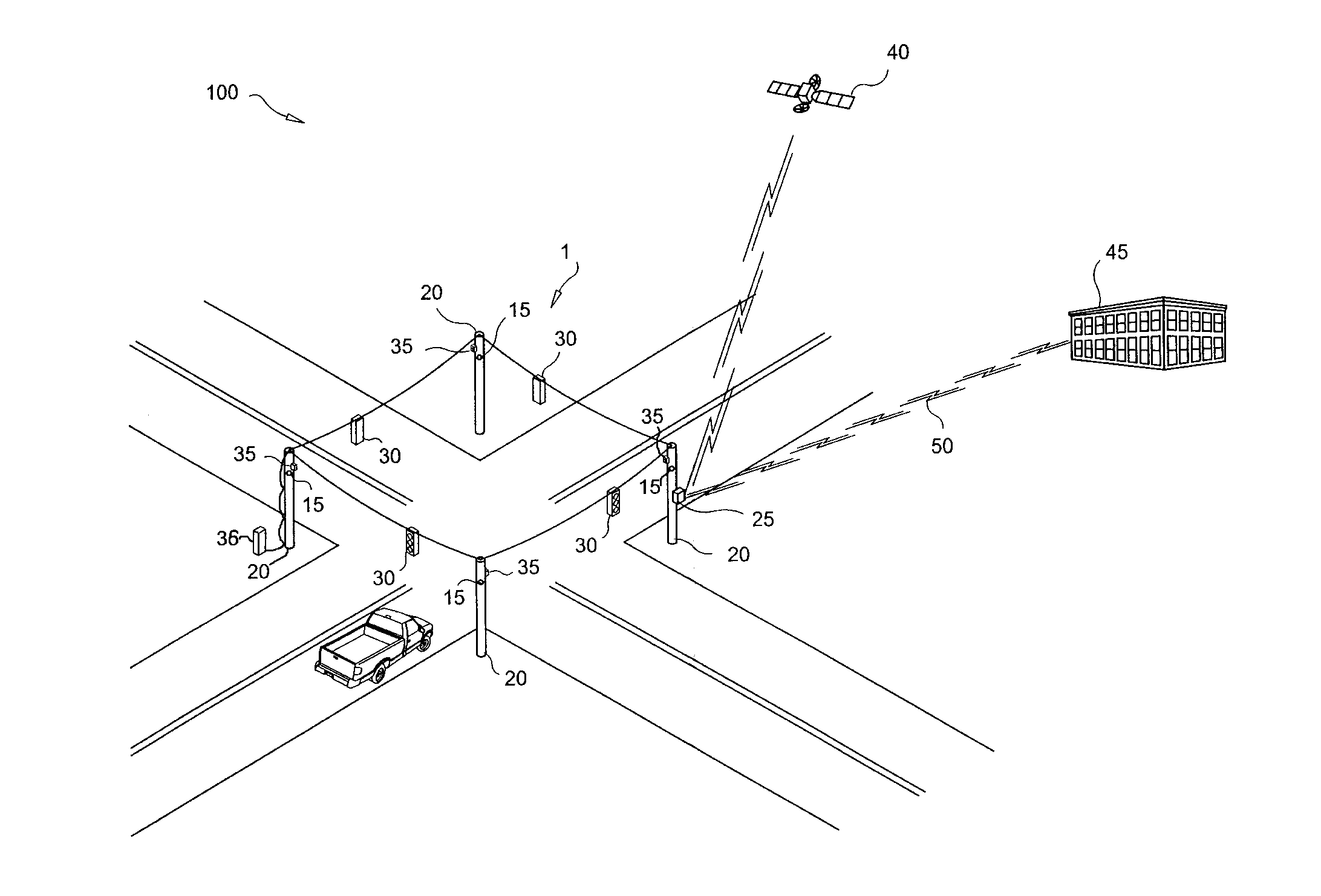
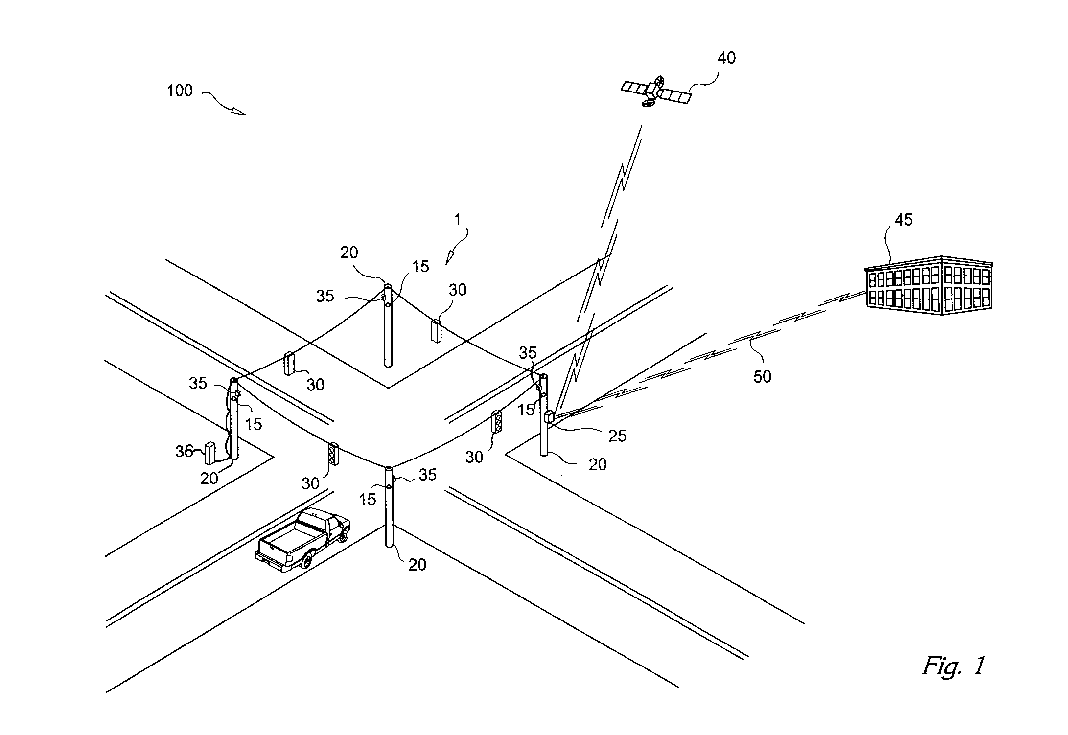
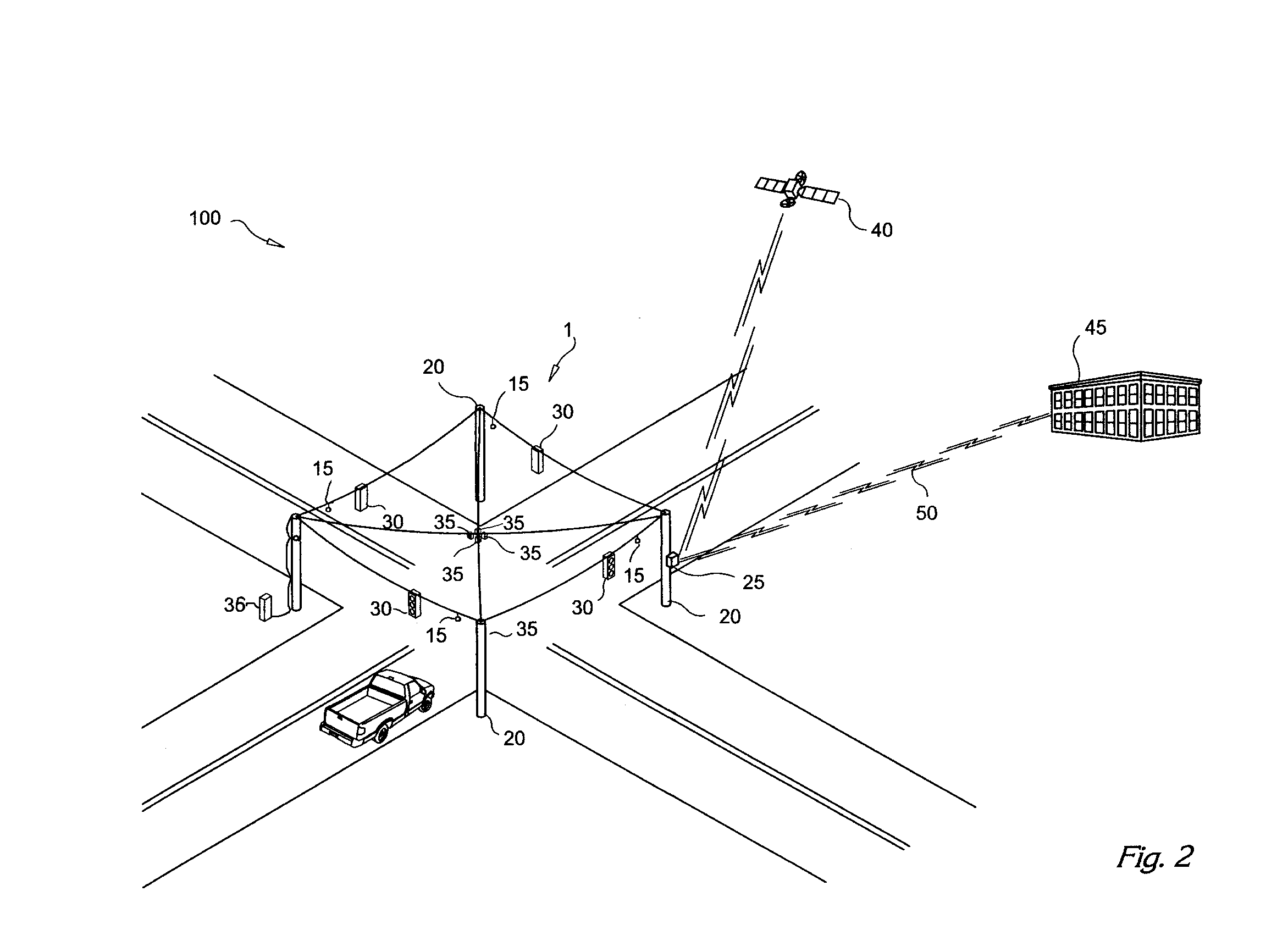
[0172]As seen in FIG. 1 the present invention is illustrated and generally designated as the system 100. The system 100 comprises one or more listening devices 15 placed proximate a traffic scene 1 which is referred to as the desired location. The desired location 1 can be any street, a section of highway, an intersection, or any other place where a traffic accident can occur. Listening devices 15, preferably microphones, are be mounted strategically at one or more positions proximate the desired location 1. In FIG. 1, the microphones 15 are place on utility poles 20, but they can be placed on any object proximate the desired location 1 such as underneath the traffic signals 30, suspended on wires above the intersection as shown in FIG. 2, or on other structures such as buildings so long as they are placed to allow accurate capture of the acoustic signals at the desired location 1.

[0173]The microphones 15 are connected to the MITS, also referred to as the control unit 25 either by w...


PUM


Abstract

A modular intelligent transportation system, comprising an environmentally protected enclosure, a system communications bus, a processor module, communicating with said bus, having a image data input and an audio input, the processor module analyzing the image data and/or audio input for data patterns represented therein, having at least one available option slot, a power supply, and a communication link for external communications, in which at least one available option slot can be occupied by a wireless local area network access point, having a communications path between said communications link and said wireless access point, or other modular components.

Description

CROSS REFERENCE TO RELATED APPLICATION[0001]The present application is a Continuation of U.S. patent application Ser. No. 15 / 173,165, filed Jun. 3, 2016, which is a Continuation of U.S. patent application Ser. No. 14 / 082,264, filed Nov. 18, 2013, now U.S. Pat. No. 9,359,018, issued Jun. 7, 2016, which is a Continuation of U.S. patent application Ser. No. 13 / 185,991, filed Jul. 19, 2011, now U.S. Pat. No. 9,371,099, issued Jun. 21, 2016, which is a Continuation of U.S. patent application Ser. No. 11 / 267,761, filed Nov. 3, 2005, now U.S. Pat. No. 7,983,835, issued Jul. 19, 2011, which claims benefit of priority from U.S. Provisional Patent Application 60 / 522,748 filed Nov. 3, 2004. U.S. patent application Ser. No. 14 / 082,255, filed Nov. 18, 2013, now U.S. Pat. No. 9,090,295, issued Jul. 28, 2015, is a Continuation of U.S. patent application Ser. No. 13 / 185,991, filed Jul. 19, 2011. Each of the foregoing is expressly incorporated herein by reference in its entirety.BACKGROUND OF THE IN...

Claims


Application Information

Patent Timeline
IPC IPC(8): G08G1/01G06K9/00G08G1/04G08G1/09G08G1/052
CPCG08G1/0116G08G1/094G08G1/052H04L65/4069G06K9/00785H04W84/12G08G1/04G08G1/205G06V20/44G06V20/54H04L65/61B64C1/00B64C39/08B64C37/02
Inventor LAGASSEY, PAUL J.
Owner THE WILFRED J AND LOUISETTE G LAGASSEY IRREVOCABLE TRUST ROGER J MORGAN TRUSTEE
Why Eureka
Try Eureka