Control apparatus

Active Publication Date: 2017-02-02
TOYOTA JIDOSHA KK
View PDF1 Cites 14 Cited by
  • Summary
  • Abstract
  • Description
  • Claims
  • Application Information

AI Technical Summary

Benefits of technology

[0016]With this configuration, downhill control is continued until the vehicle passes through the end point of the initially determined controlled target section, and, even when a downhill section that can be the controlled target section subsequent to the end point of the initially d

Problems solved by technology

On the other hand, it is known that a repetitive change in an extremely large remaining amount of charge (hereinafter, also simply referred to as state of charge (SOC)) or extremely small remaining amount of charge of the storage battery accelerates the performance degradation of the storage battery.
At this time, electric energy that is generated as a result of regenerative braking is transformed into thermal energy in a friction brake device or an inverter or both, or the like, so energy originally recoverable and usable for propelling the vehicle is consumed uselessly.
As a result, fuel is consumed due to a cause other than propelling the vehicle.
Therefore, when the vehicle travels on a long downhill (that is, a section having a relatively long distance and

Method used


Image

  • Control apparatus
  • Control apparatus
  • Control apparatus

Examples


Example

First Embodiment

Configuration

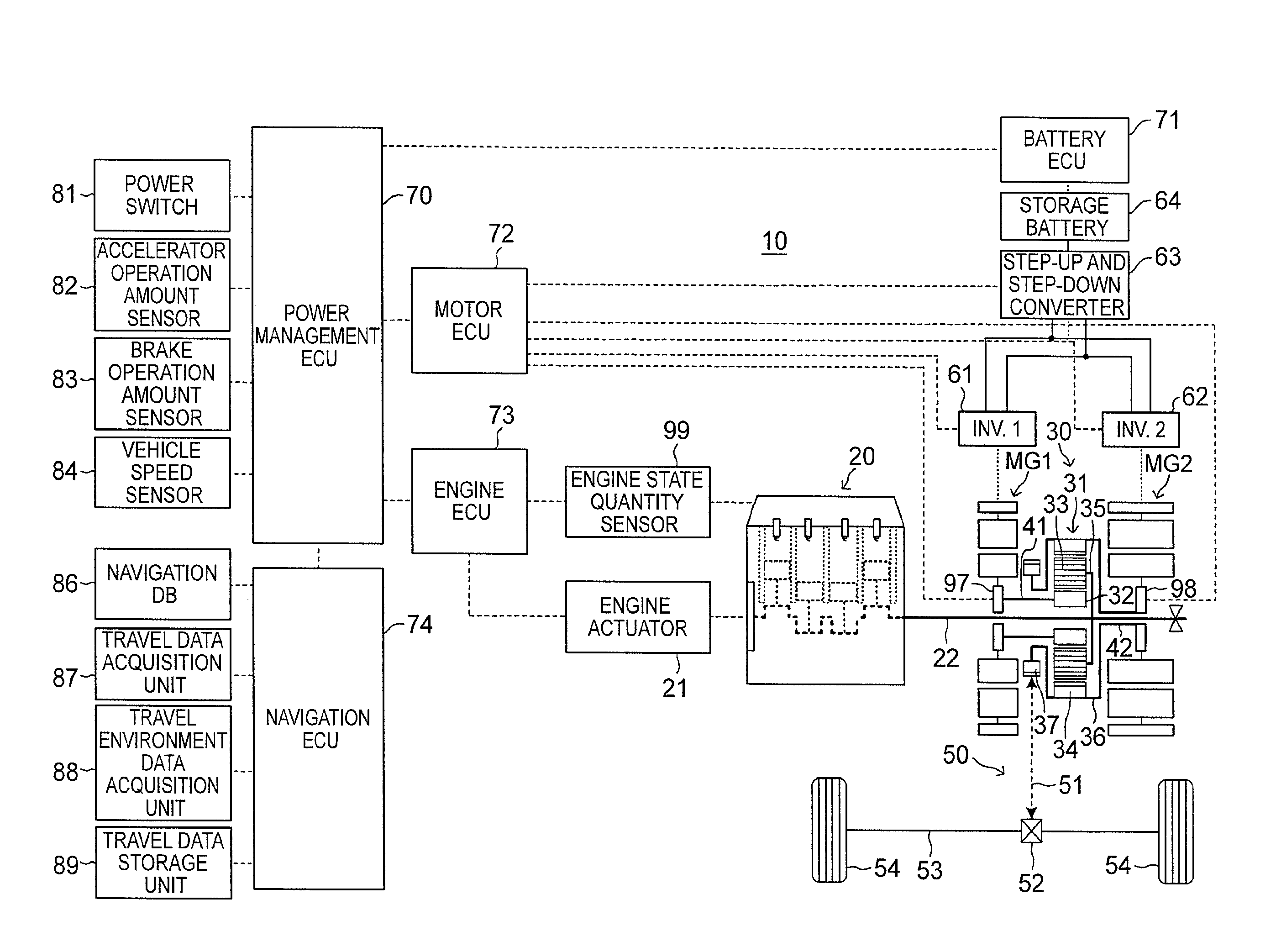
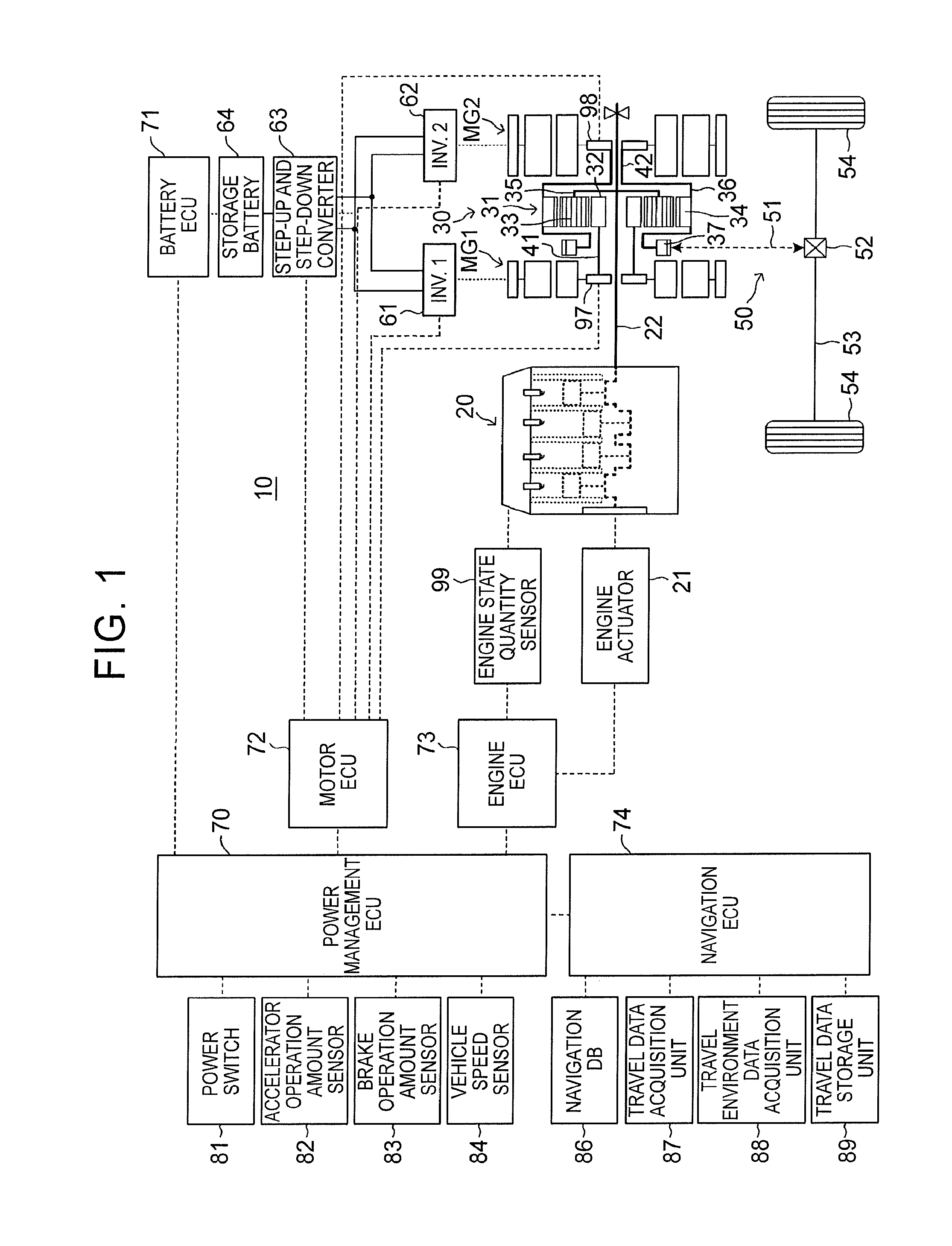
[0031]A control apparatus (hereinafter, referred to as first apparatus) for a hybrid vehicle according to the first embodiment of the present disclosure is applied to a hybrid vehicle 10 (hereinafter, also simply referred to as vehicle) shown in FIG. 1.

[0032]The vehicle 10 includes a first generator motor MG1, a second generator motor MG2, an internal combustion engine 20, a power split mechanism 30, a driving force transmission mechanism 50, a first inverter 61, a second inverter 62, a step-up and step-down converter 63, a storage battery 64, a power management ECU 70, a battery ECU 71, a motor ECU 72, an engine ECU 73, a navigation ECU 74, and the like. These ECUs may be integrated as one ECU, and correspond to a controller according to the present disclosure.

[0033]The ECU is an abbreviation of electronic control unit. The ECU is an electronic control circuit including a microcomputer as a main component. The microcomputer includes a CPU, a ROM, a RAM,...

Example

Second Embodiment

[0140]A control apparatus (hereinafter, referred to as second apparatus) for a hybrid vehicle according to a second embodiment of the present disclosure differs from the first apparatus only in that the NV ECU 74 (actually, the CPU) immediately executes the routine shown in FIG. 6 not only each time a predetermined time elapses but also at a point in time at which the vehicle 10 has passed through the end point De of the controlled target section (the end point of the target downhill section).

[0141]That is, a controller of the second apparatus immediately starts the process of the routine shown in FIG. 6 at the point in time at which the vehicle 10 has passed through the end point De of the controlled target section for which downhill control is started (including timing just after that point in time), and newly determines a controlled target section. Therefore, even when a downhill section that can be the controlled target section subsequent to the end point De of ...


PUM


Abstract

A control apparatus and method for a hybrid vehicle that searches for and determines a scheduled travel route and a downhill section included in the scheduled travel route on the basis of positional information of the vehicle and road information. The control apparatus determines a section from a downhill control start point to an end point of a target downhill section as a controlled target section. The downhill control start point is located a predetermined first distance before a start point of the target downhill section. When the vehicle travels on the controlled target section, the control apparatus executes downhill control. Even in a situation in which a target downhill section is newly determined during execution of the downhill control, the control apparatus continues the downhill control until the vehicle reaches an end point of the controlled target section for which the downhill control is started.

Description

INCORPORATION BY REFERENCE[0001]The disclosure of Japanese Patent Application No. 2015-152892 filed on Jul. 31, 2015 including the specification, drawings and abstract is incorporated herein by reference in its entirety.BACKGROUND OF THE DISCLOSURE[0002]1. Field of the Disclosure[0003]The present disclosure relates to a control apparatus for a hybrid vehicle including an internal combustion engine, an electric motor and a storage battery that supplies electric power to the electric motor.[0004]2. Description of Related Art[0005]Conventionally, a hybrid vehicle (hereinafter, also simply referred to as vehicle) travels while controlling an electric motor and an internal combustion engine such that the capacity of a chargeable and dischargeable storage battery is efficiently utilized for the purpose of improvement in the fuel consumption performance of the vehicle.[0006]On the other hand, it is known that a repetitive change in an extremely large remaining amount of charge (hereinafter...

Claims


Application Information

Patent Timeline
IPC IPC(8): B60W20/14B60W10/26B60W10/08B60W20/12B60W10/06B60L50/16
CPCB60W20/14B60W20/12B60W10/06B60W10/08B60W10/26B60W2530/00B60Y2300/181B60W2710/06B60W2710/08B60W2710/244B60W2550/402B60Y2200/92B60W2550/142B60K6/24B60K6/26B60K6/28B60L7/10B60W20/00B60W30/18127B60W40/06B60W40/10B60W2710/242B60K6/445B60W2552/15B60W2552/20B60W2552/25B60W2556/50Y02T10/62Y02T10/72
Inventor OGAWA, YUKIKATO, MITSUHARU
Owner TOYOTA JIDOSHA KK
Why Eureka
Try Eureka