Device for extending the exit pupil and head up display comprising said device

a head-up display and exit pupil technology, applied in the field of optical exit pupil expansion devices, can solve the problems of large optical system exit pupil using conventional spherical lenses that are relatively complex and bulky

Inactive Publication Date: 2017-02-02
COMMISSARIAT A LENERGIE ATOMIQUE ET AUX ENERGIES ALTERNATIVES
View PDF11 Cites 12 Cited by
  • Summary
  • Abstract
  • Description
  • Claims
  • Application Information

AI Technical Summary

Benefits of technology

[0009]An object of an embodiment is to provide a head-up display overcoming all or part of the disadvantages of existin

Problems solved by technology

However, optical systems having a large exit pupil using con

Method used


Image

  • Device for extending the exit pupil and head up display comprising said device
  • Device for extending the exit pupil and head up display comprising said device
  • Device for extending the exit pupil and head up display comprising said device

Examples


Embodiment Construction

[0032]For clarity, the same elements have been designated with the same reference numerals in the different drawings. Further, the various drawings are not to scale. Further, in the following description, unless otherwise indicated, terms “approximately”, “substantially”, “around”, and “in the order of” mean “to within 10%”, and terms referring to directions, such as topping, lateral, above, under, upper, lower, vertical, horizontal, etc. apply to devices and systems oriented as illustrated in the corresponding views, it being understood that, in practice, the described devices and systems may have different directions.

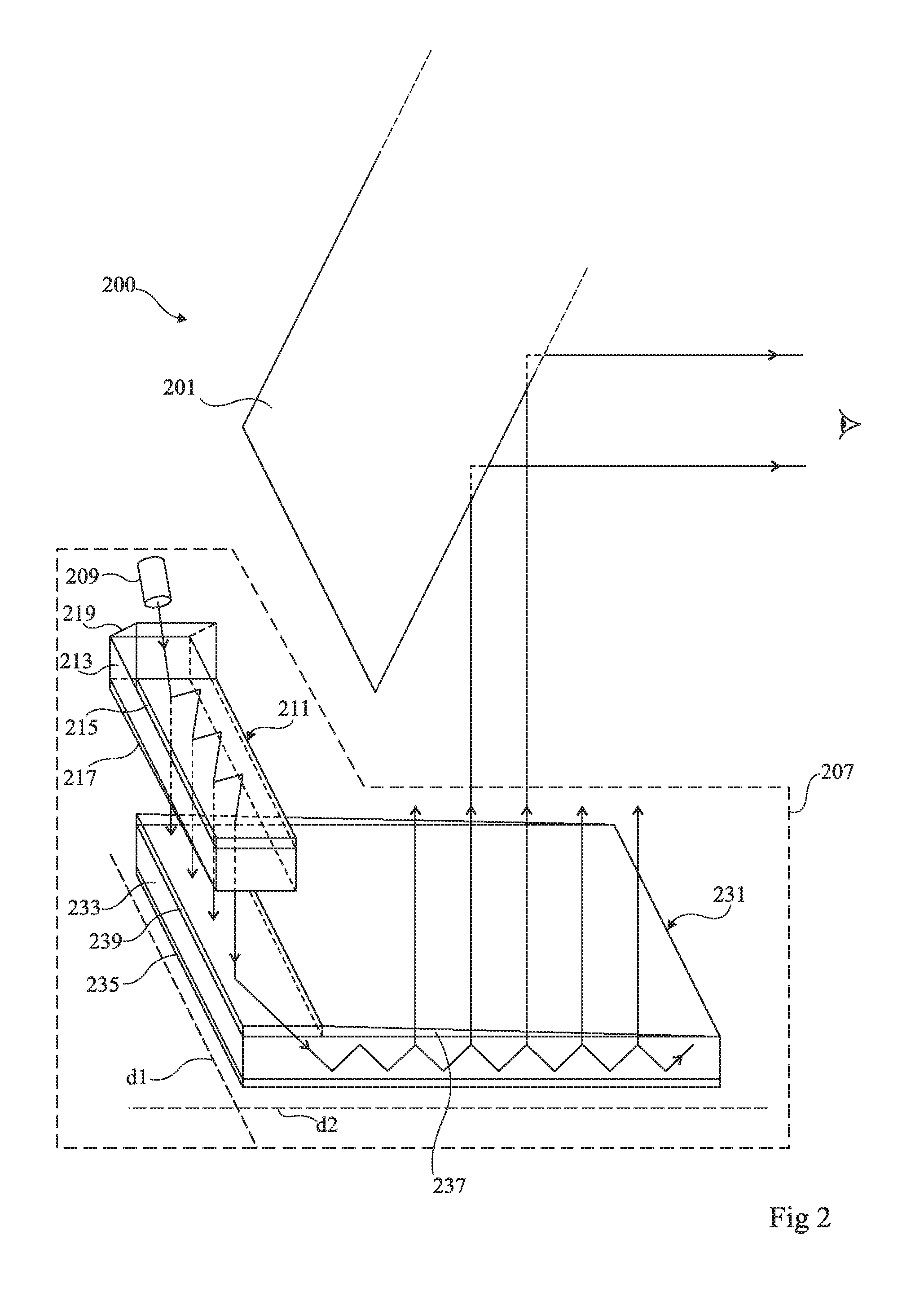
[0033]FIG. 2 is a perspective view schematically illustrating the operation of an embodiment of a head-up display 200.

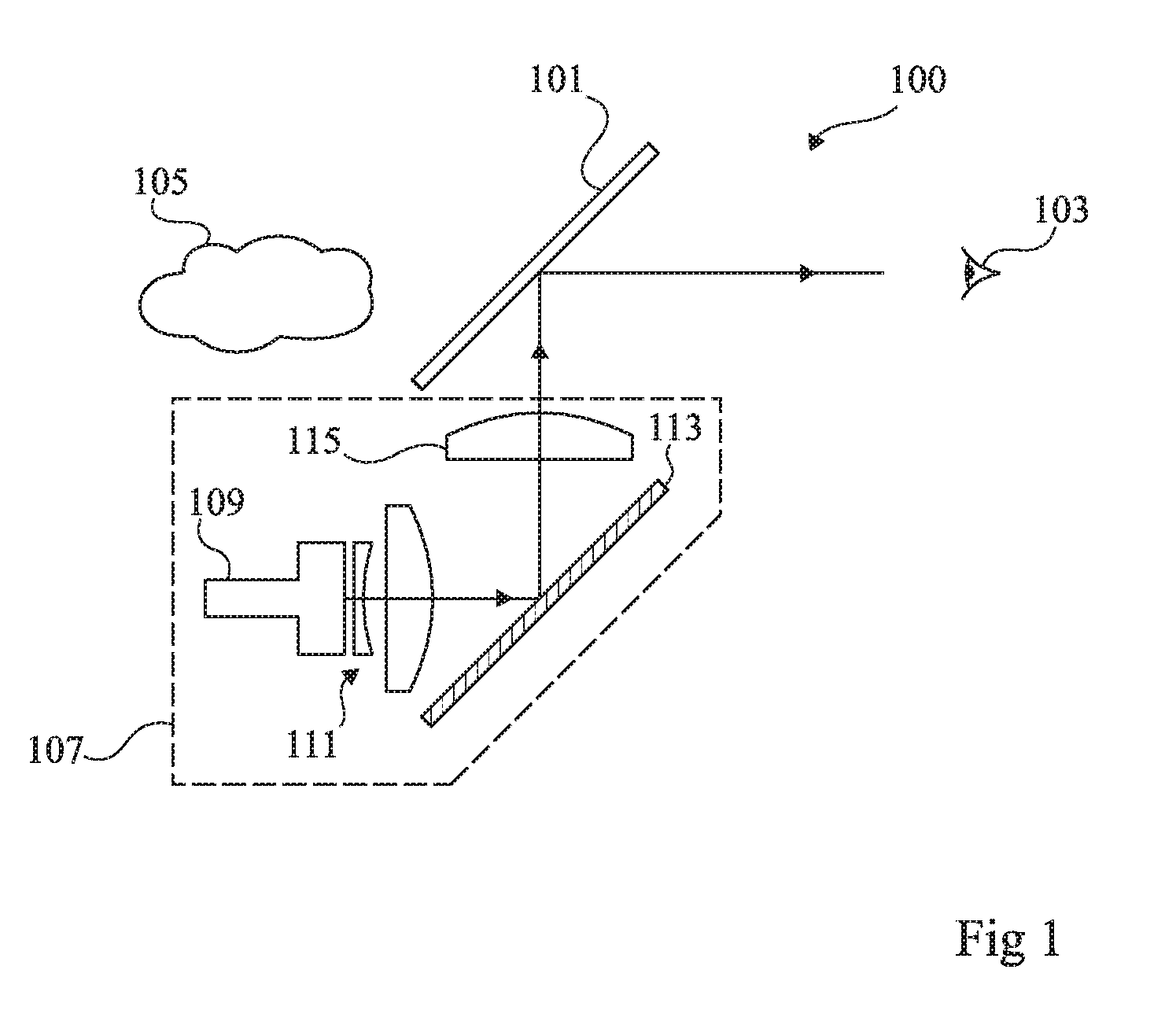
[0034]Head-up display 200 comprises a beam splitter or semi-transparent plate 201 intended to be placed between the eye of a user 203 and a scene to be observed (not shown in FIG. 2). Beam splitter 201 may be placed according to an angle of approximate...


PUM


Abstract

An optical device comprises a transparent blade the first surface of which is reflective; a first partially reflective and partially transmissive layer covering a second surface of the transparent blade opposite the first surface, and a second layer covering the surface of the first layer opposite the transparent blade, wherein the second layer is made of a material having an optical index which differs from the optical index of the transparent blade by less than 10% and preferably by less than 5%, and the second layer comprises, on the surface thereof opposite the first layer, structures forming a diffraction grating suitable for promoting the extraction of light towards the outside of the transparent blade.

Description

BACKGROUND[0001]The present application relates to an optical exit pupil expansion device. It also aims at an image projection system comprising such an optical device and to a head-up display comprising such an image projection system.DISCUSSION OF THE RELATED ART[0002]Head-up displays, also known as HUDs, are augmented reality display systems which enable to overlay visual information on a real scene seen by an observer. In practice, such systems may be placed in the cockpit of a plane or in the interior of a vehicle.[0003]FIG. 1 schematically illustrates the operation of a conventional head-up display 100.[0004]A beam splitter 101 is placed between the eye of a user 103 and a scene to be observed 105. The objects of the scene to be observed are for example located at infinity or at a long distance from the observer. Beam splitter 101 may be placed according to an approximate 45° angle relative to the axis between scene 105 and observer 103 to transmit the information originating ...

Claims


Application Information

Patent Timeline
IPC IPC(8): G02B27/01G02B27/00G02B27/42
CPCG02B2027/015G02B27/0081G02B27/4205G02B27/0101G02B6/0028G02B6/005G02B2027/0125G02B27/0172G02B6/0055
Inventor ROSSINI, UMBERTO
Owner COMMISSARIAT A LENERGIE ATOMIQUE ET AUX ENERGIES ALTERNATIVES
Why Eureka
Try Eureka