
Small animal imaging device

a small animal and imaging device technology, applied in the field of masks, can solve the problems of many problems and limitations, masks are too simple to handle dangerous gas(es), and design is only satisfactory for imaging rodents in a prone position

Inactive Publication Date: 2017-02-09
ROSEMAN JACK G
View PDF2 Cites 7 Cited by
  • Summary
  • Abstract
  • Description
  • Claims
  • Application Information

AI Technical Summary

Benefits of technology

The present invention is directed to a new anesthesia mask for animals used in medical imaging. The mask is designed to improve the stability of the animal's head during imaging and to minimize motion caused by respiration (breathing) while in a prone position. Current masks are either too simple or too complex and not user-friendly. The new mask is designed to collect and remove unused gas, is configured to function in both prone and supine positions, and includes a system for collecting gas. The technical effects of the invention include improved stability of the animal's head, reduced motion caused by respiration, and improved gas delivery for animal anesthesia.

Problems solved by technology

Unfortunately, currently available anesthesia masks used by research facilities are too simple to handle dangerous gas(es), or too complex and not user-friendly.
Unfortunately, such masks have many problems and limitations.
Additionally, this design is only satisfactory for imaging rodents in a prone position because the design relies on gravity to keep the head fixed on the bite bar mechanism and the incisors hooked onto the bite bar mechanism.
In the prone position, normal respiration causes chest and underside contractions that can cause unwanted head movement, resulting in motion artifacts in the images and, thus, lower quality scans.
Unfortunately, time is often wasted trying to place the animal in position where the animal is completely still and remains unaffected by external forces.
Further, as a result of their simple construction, currently available masks are not made to handle dangerous gas(es).
In fact, it is inaccurate to refer to them as being “gas masks” because many of them do not deliver gas correctly, efficiently, or safely.
In many current designs, using the aforementioned positioning mechanism, the animal's head is suspended in the mask, leaving a void in which dangerous gas(es) may collect before being inhaled.
Most existing masks are not configured to collect and remove unused gas, because such a mechanism is too complex, which may allow dangerous anesthesia gas(es) to leak into the environment.
This also reduces the efficacy of gas delivery.
More complex and expensive gas-delivery apparatuses that use a valved system to deliver and collect gas are available and solve the problem of anesthesia gas(es) leaking into the environment.
Unfortunately, the valves in these designs rely on the misconception that all mice breathe nasally, which renders such designs useless for experimental animals that breathe orally.
While the more advanced apparatuses are better than the simpler designs in terms of head stability, they similarly do not give users full autonomy to change the position of the animal (e.g., from prone to supine and vice versa) to limit respiration-induced motion.

Method used


Image

  • Small animal imaging device
  • Small animal imaging device
  • Small animal imaging device

Examples


Embodiment Construction

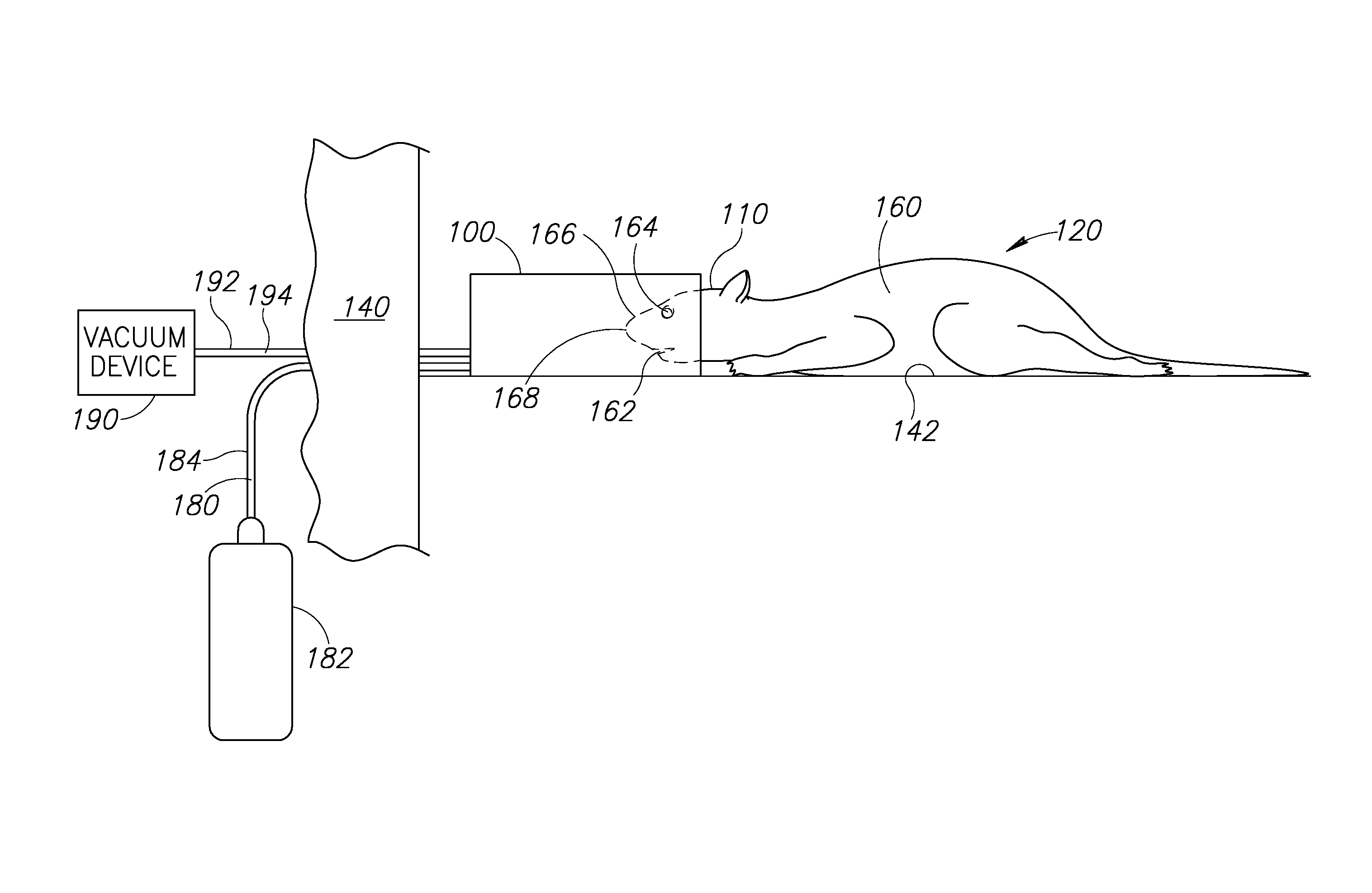
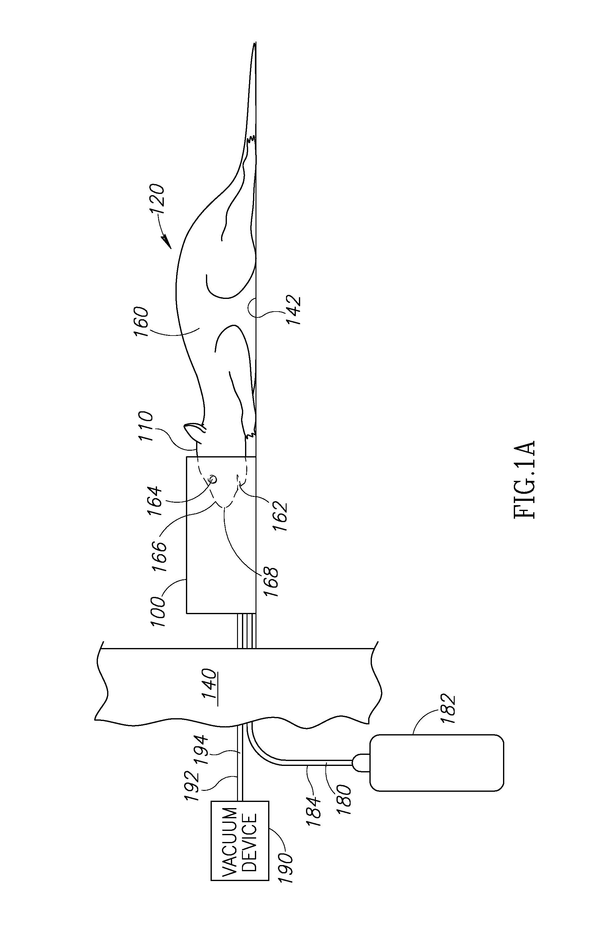
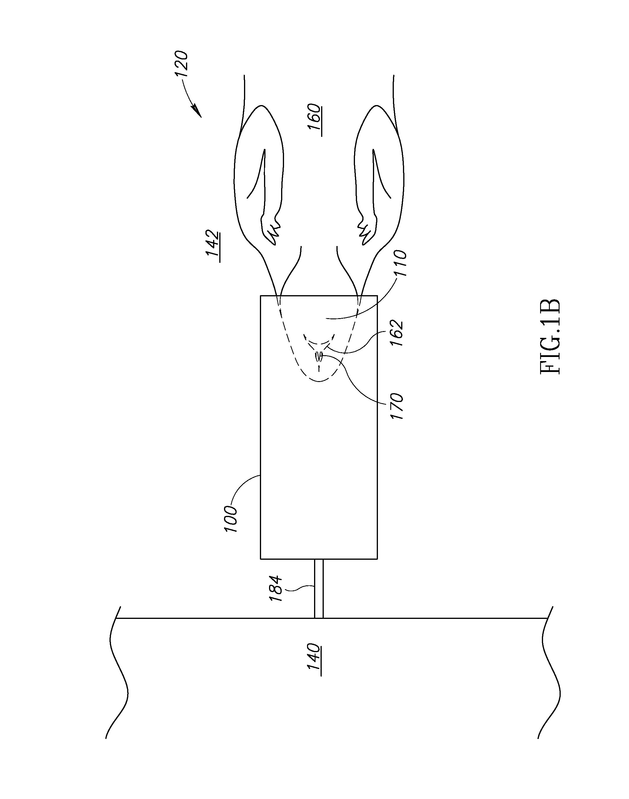
[0021]FIG. 1A is a side view of a Small Animal Imaging Device (“SAID”) 100 shown on a head 110 of an animal 120. In FIGS. 1A and 1B, the SAID 100 is illustrated before the animal 120 is imaged by an imaging device 140. By way of non-limiting examples, the imaging device 140 may be a magnetic resonance imaging (“MRI”) machine, a computerized tomography (“CT”) machine, a positron emission tomography (“PET”) machine, and the like. The imaging device 140 is configured to produce a scan of all or a portion of the animal 120 when the animal 120 is anesthetized. When being imaged by the imaging device 140, the animal 120 is positioned on a bed 142 in a desired imaging position (e.g., prone or supine). In FIG. 1A, the animal 120 is depicted in the prone position. However, this is not a requirement. The animal 120 may alternatively be positioned in a supine position (see FIG. 1B), on its side, and the like. The SAID 100 may be “machine-compatible” meaning the SAID 100 may be configured for u...


PUM


Abstract

An anesthesia mask configured to be worn on an animal's head. The mask includes a contoured surface that substantially follows the contours of a portion of the animal's head and defines a cavity that at least partially receives the head. One or more outlets in communication with the nose and / or the mouth are formed in the contoured surface. The mask includes a first opening configured to receive anesthesia and at least one channel that conducts the anesthesia from the first opening to the outlet(s). The mask may include an airflow collection system that includes inlet(s) formed in the contoured surface, a second opening connectable to a vacuum device, and passageway(s) configured to conduct an unused portion of the anesthesia from the inlet(s) to the second opening. The mask may include a body portion and a removable bite bar component that include first and second portions, respectively, of the contoured surface.

Description

BACKGROUND OF THE INVENTION[0001]Field of the Invention[0002]The present invention is directed generally to masks used to deliver anesthesia and more particularly to masks used to anesthetize animals (e.g., mice and rats).[0003]Description of the Related Art[0004]Gas is used to anesthetize rodents and other small animals during imaging (e.g., fully body scans) to minimize body motion and capture higher quality scans with fewer artifacts caused by unwanted motion. Standard protocols for imaging such animals for cancer research include anesthetization using an anesthesia mask compatible with the particular scanning technology being used. Unfortunately, currently available anesthesia masks used by research facilities are too simple to handle dangerous gas(es), or too complex and not user-friendly.[0005]Currently available masks utilize a bite bar mechanism to fix a rodent's head inside a cylindrically shaped or cone shaped chamber that approximates the largest dimension of the head, al...

Claims


Application Information

Patent Timeline
Patent Type & Authority Applications(United States)
IPC IPC(8): A61M16/06A61B6/00A61B5/055A61B6/03A61M16/01A61M16/00
CPCA61M16/0683A61M16/01A61M16/0093A61B5/055A61B2503/40A61B6/037A61B6/508A61M2250/00A61B6/032A61D7/04A61M16/009A61M16/06
Inventor ROSEMAN, JACK G.
Owner ROSEMAN JACK G
Learn More