Method, a rope terminal arrangement and an elevator

a technology of terminal arrangement and elevator, which is applied in the direction of elevators, vehicles/pulleys, textile cables, etc., can solve the problems of difficulty in simple and reliable grip, loss of suspension of particular ropes, and special ropes which may be damaged, etc., to facilitate easy installation, reduce risks, and reduce risk.

Inactive Publication Date: 2017-02-09
KONE CORP
View PDF2 Cites 27 Cited by
  • Summary
  • Abstract
  • Description
  • Claims
  • Application Information

AI Technical Summary

Benefits of technology

[0008]It is brought forward a new method for fabricating a rope terminal arrangement of an elevator for fixing an end of a belt-shaped elevator rope to a fixing base, comprising providing a belt-shaped elevator rope comprising a coating forming the outer surface of the rope; providing at least one gripping member having a gripping face; providing a wedge frame delimiting a wedge-shaped space; placing the gripping face of each said gripping member against the coating of a rope section of the belt-shaped rope; bonding the gripping face of each said gripping member and the coating of the rope section together. The method further comprises, in particular and subsequent said bonding, wedging the at least on

Problems solved by technology

In prior art, such special ropes are known which may be damaged if sharp bends are caused in them.
The rope end should be firmly gripped such that it can't slide out of the compression gap, because this would mean that the suspension of the particular rope would be lost.
This kind of rope terminal arrangement has the drawback that a reliable grip is difficult to provide simply.
The surface material is subjected to continuous compression and shear stress, which may cause increasing deformation over time (creep).
In long term, the creep phenomenon can lead to slipp

Method used


Image

  • Method, a rope terminal arrangement and an elevator
  • Method, a rope terminal arrangement and an elevator
  • Method, a rope terminal arrangement and an elevator

Examples


Embodiment Construction

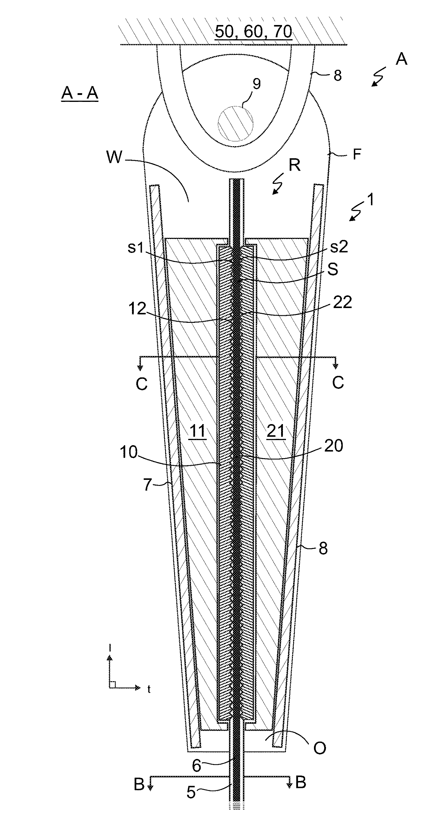
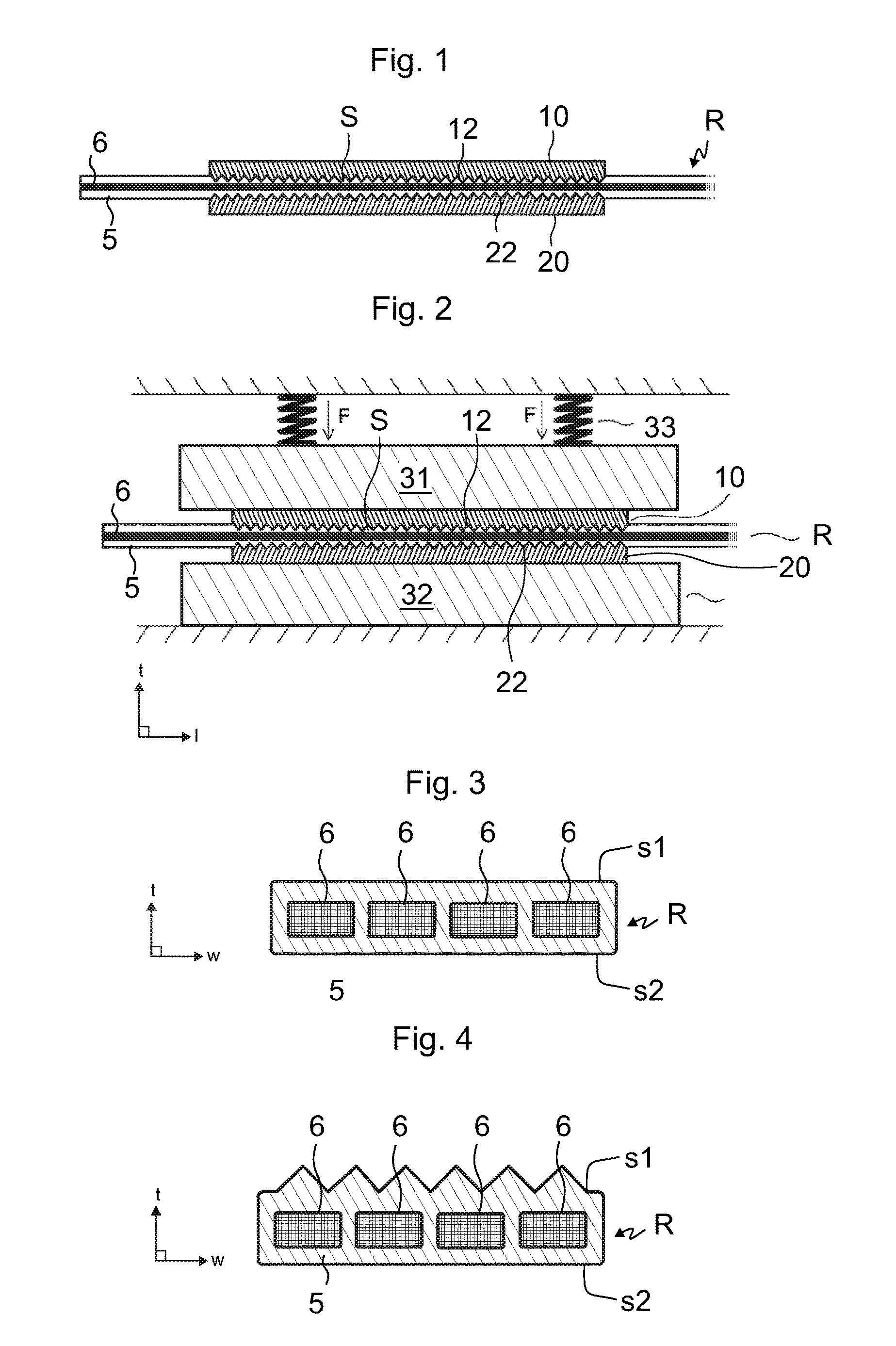
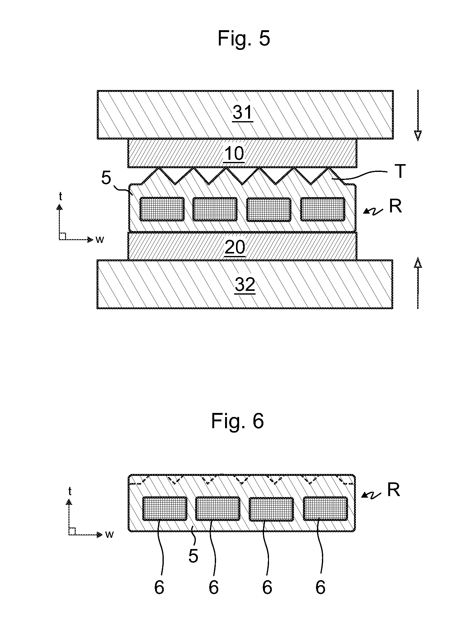
[0064]FIG. 1 illustrates a stage of a preferred embodiment of a method for fabricating a rope terminal arrangement A for fixing an end of a rope R of an elevator to a fixing base of an elevator. The rope terminal arrangement A being fabricated is one utilizing wedging of a rope section S of the rope R in a wedge space. In the method a belt-shaped elevator rope R is provided, the rope R comprising a coating 5 forming the outer surface of the rope R. One or more load bearing members 6 may be embedded in the coating, as will be later explained, whereby a proper load bearing ability for the rope R is established.

[0065]In the method, at least one gripping member 10,20 having a gripping face 12,22 is furthermore provided. The gripping face 12,22 of each said gripping member 10,20 is then placed against the coating 5 of a rope section S of the belt-shaped rope R, which rope section S is intended to be gripped by the at least one gripping member 10,20, such that the coating 5 and the grippi...


PUM


Abstract

The invention relates to a method for fabricating a rope terminal arrangement of an elevator, comprising
    • providing a belt-shaped elevator rope comprising a coating forming the outer surface of the rope;
    • providing at least one gripping member having a gripping face;
    • providing a wedge frame delimiting a wedge-shaped space;
    • placing the gripping face of each said gripping member against the coating of a rope section of the belt-shaped rope;
    • bonding the gripping face of each said gripping member and the coating of the rope section together;
    • wedging the at least one gripping member and the rope section in the wedge shaped space.
The invention furthermore relates to a rope terminal arrangement fabricated with the method, as well as to an elevator implementing the rope terminal arrangement.

Description

[0001]This application claims priority to European Patent Application No. 15180136.2 filed on Aug. 7, 2015, the entire contents of which are incorporated herein by reference.FIELD OF THE INVENTION[0002]The invention relates to fixing of elevator ropes, more specifically to fabrication of a rope terminal arrangement of an elevator, wherein the elevator is in particular of a kind suitable for transporting passengers and / or goods.BACKGROUND OF THE INVENTION[0003]In elevators, ropes are used as the means by which the elevator car is suspended. Ropes are further used as the means by which motive force is transmitted to the elevator car. Each rope typically has two ends, and each end needs to be fixed to a fixing base, which is typically either the load to be lifted or a stationary structure, depending on the type of suspension chosen for the elevator. The rope ends can be fixed directly to the load, such as the car or counterweight, which is the case when these are to be suspended with 1...

Claims


Application Information

Patent Timeline
IPC IPC(8): B66B7/08F16G11/04
CPCB66B7/085B66B9/00F16G11/044
Inventor LEHTINEN, HANNUHALLIKAINEN, PEKKA
Owner KONE CORP
Why Eureka
Try Eureka