Stucco Crack Reduction at Corners

a crack reduction and stucco technology, applied in the direction of covering/lining, construction, building construction, etc., can solve the problems of unsightly stucco cracks, uneven displacement of framing members within the stucco system, and failure to effectively so as to reduce the risk of cracks or eliminate them. , the effect of less flammability

Active Publication Date: 2017-02-09
GOMES HAROLD FURTADO
View PDF0 Cites 4 Cited by
  • Summary
  • Abstract
  • Description
  • Claims
  • Application Information

AI Technical Summary

Benefits of technology

[0028]A next step may include the application of a first coat or scratch coat over the building paper, metal lath and corner elements. The material of the scratch coat may penetrate voids of the corner elements. Such voids may include a center void, a plurality of circular voids and circle voids. Dimples may be found upon the topside of the crown section. Subsequent coats may be applied as usual. But, the us

Problems solved by technology

The prior art recognizes but yet fails to effectively address the fact that during building movement, door and window frames will buckle or move outwardly at corner junctures causing an uneven displacement of the framing members within the stu

Method used


Image

  • Stucco Crack Reduction at Corners
  • Stucco Crack Reduction at Corners
  • Stucco Crack Reduction at Corners

Examples


second embodiment

[0135]FIGS. 18 to 23 depict an alternative embodiment or a second embodiment having the same or similar attributes and advantages of the other disclosed embodiments.

third embodiment

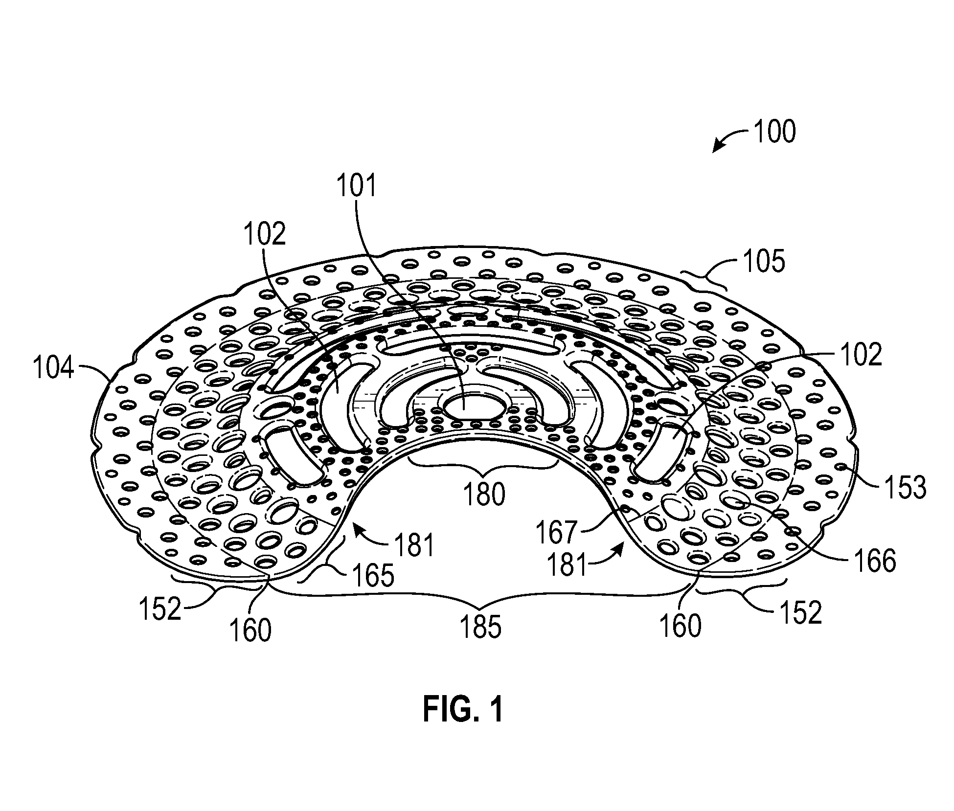
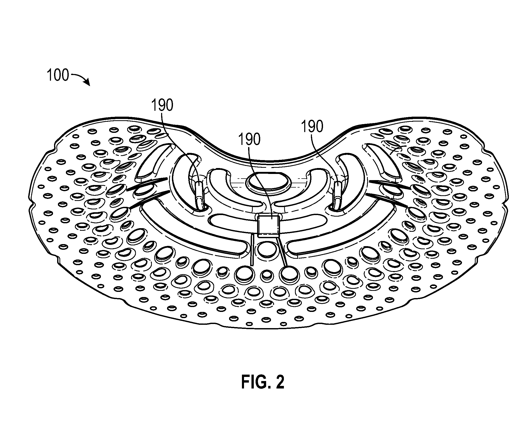
[0136]FIG. 24 depicts a third embodiment having a plurality of eyebrow void assemblies 130, the eyebrow void assemblies comprising a horizontally disposed center or horizontal void. A raised arc 134 may be centrally disposed over a horizontal void, with the raised arc 134 defining a vertically defined void 136.

[0137]The disclosed eyebrow assembly represents a significant breakthrough in the art, as the stucco cracks are eliminated or greatly reduced as the raised arc 134 is able to adhere within the stucco significantly better as compared to the first and second embodiments herein. The raised arc 134 placed over a horizontal void 132 allows the corner element to embed in the stucco in three dimensions, producing improved results over the prior art and over the first two embodiments disclosed herein. The eyebrow assemblies may be located or defined anywhere upon or within a corner element.

[0138]In the depicted third embodiment, starting at FIG. 24, the eyebrow assemblies are illustra...


PUM


Abstract

Stucco cracks at doors and windows are reduced or eliminated by use of a corner element fastened at a corner juncture before stucco coats are applied. The disclosed corner element spreads out or evenly dissipates differential movement or buckling often occurring at exterior corner junctures. The corner element may comprise various concentric circle attributes useful in stopping or reducing cracks in stucco and related building materials. The corner element embodiments may be secured at widow and door corner areas and then integrated with traditional stucco applications.

Description

[0001]RELATED PATENT APPLICATIONS AND INCORPORATION BY REFERENCE[0002]This utility patent application is a continuation in part of design patent application Ser. No. 29 / 526,176 filed on Aug. 13, 2015 which is a continuation in part application Ser. No. 29 / 477,998 filed on Dec. 30, 2013, now U.S. Pat. No. D739039, which is a continuation in part of application Ser. No. 13 / 769,536 filed on Feb. 18, 2013, now U.S. Pat. No. 8,615,950. These related patent applications and patents are incorporated herein by reference and made part of this utility application as if fully set forth herein. Moreover, the inventor incorporates herein by reference any and all patents, patent applications, and other documents hard copy or electronic, cited or referred to in this application.COPYRIGHT AND TRADEMARK NOTICE[0003]This application includes material which is subject or may be subject to copyright and / or trademark protection. The copyright and trademark owner(s) has no objection to the facsimile repr...

Claims


Application Information

Patent Timeline
IPC IPC(8): E04F13/06
CPCE04F2013/063E04F13/06
Inventor GOMES, HAROLD FURTADO
Owner GOMES HAROLD FURTADO
Why Eureka
Try Eureka