Light-emitting diode modules

Active Publication Date: 2017-02-09
SCHREDER SA
View PDF3 Cites 9 Cited by
  • Summary
  • Abstract
  • Description
  • Claims
  • Application Information

AI Technical Summary

Benefits of technology

[0009]It is therefore an object of the present invention to provide a simple arra

Problems solved by technology

The window, whilst allowing light from the LED modules to be transmitted from the enclosure, forms another optical interface which generates additional light losses due to attenuation.
However, whilst such a solution is suitable for LED modules having their own thermal heat sinks, it complicates the assembly of flat LED modules when they need to be mounted to a flat surface of a luminaire body as grooves and holes need to be provided to allow for the routing of wires and cables to

Method used


Image

  • Light-emitting diode modules
  • Light-emitting diode modules
  • Light-emitting diode modules

Examples


Example

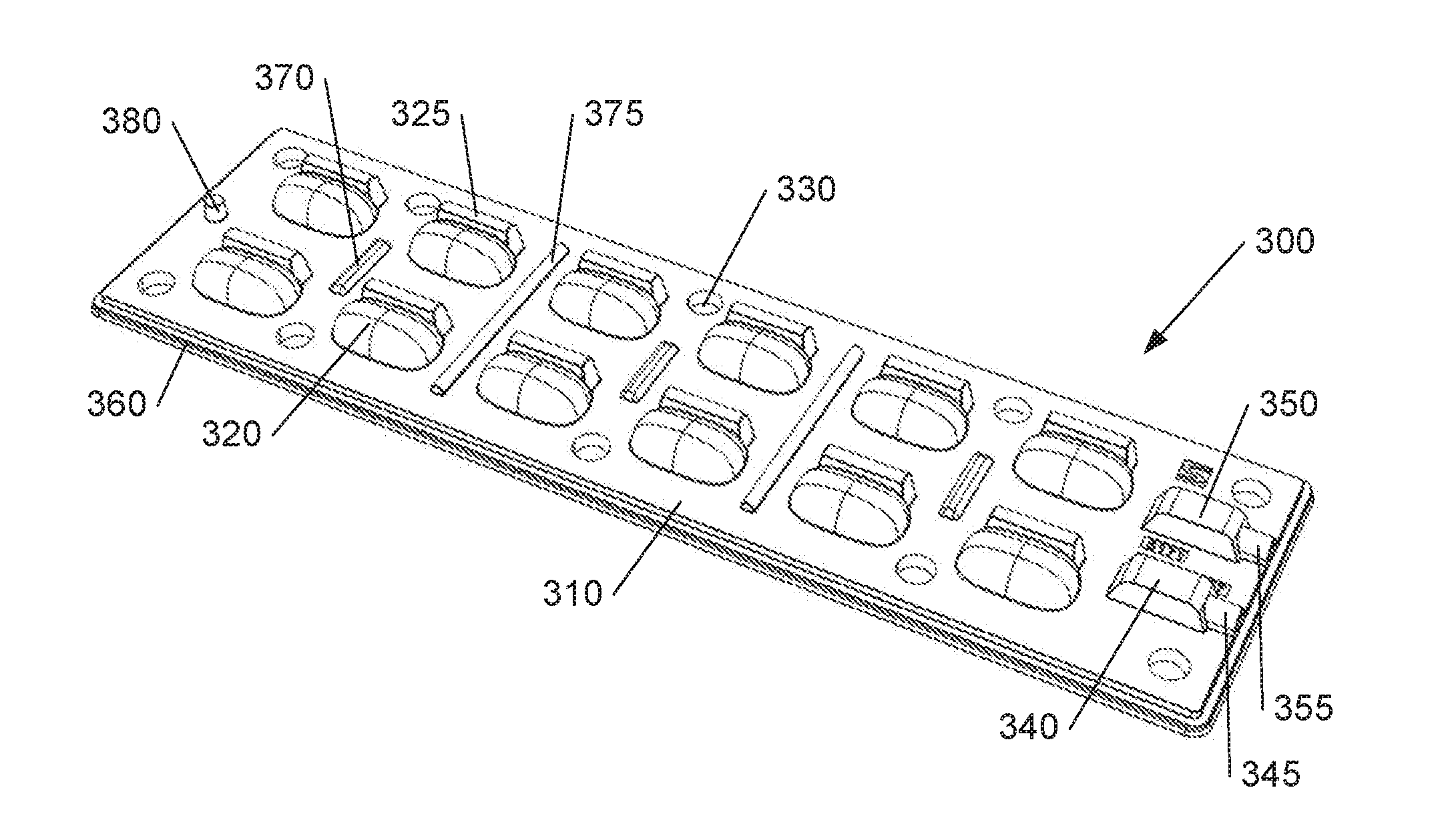
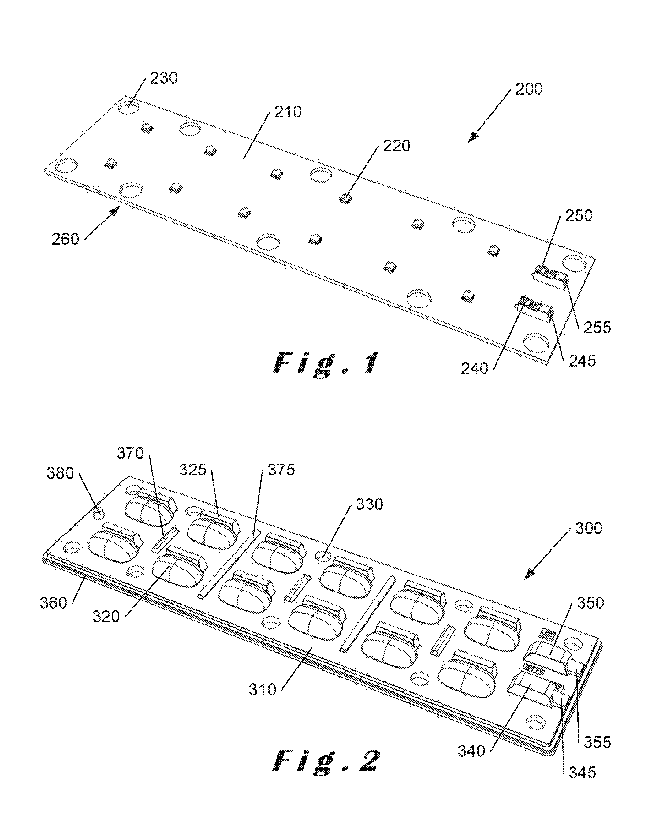
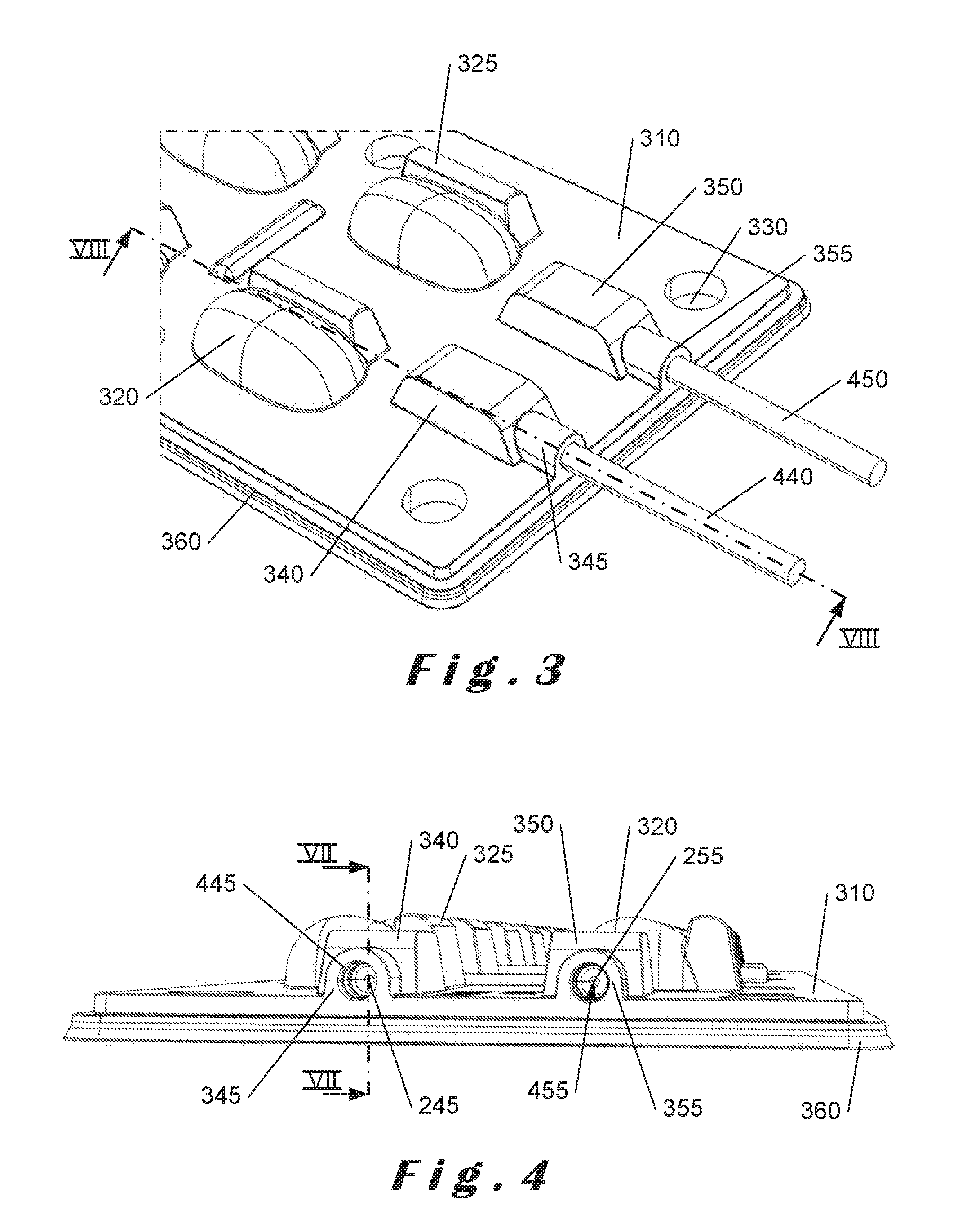
[0060]The present invention will be described with respect to particular embodiments and with reference to certain drawings but the invention is not limited thereto. The drawings described are only schematic and are non-limiting. In the drawings, the size of some of the elements may be exaggerated and not drawn on scale for illustrative purposes.

[0061]Although the present invention will be described with reference to LED modules suitable for luminaires, it will readily be appreciated that the invention is not limited to such an implementation and can be used in any LED module, particularly if it requires prevention of water ingress.

[0062]The terms “printed circuit board assembly” and “PCBA” as used herein refer to a printed circuit board (PCB) on which an array of LED elements are mounted. These terms also include wiring connections to provide power to each LED element.

[0063]The term “light-emitting light diode module” or “LED module” as used herein refers to a PCBA, a secondary len...


PUM


Abstract

Described herein is an LED module (500) comprising a PCBA (200) having an array of LED elements, a secondary lens array (300) and a lens holder (510). The secondary lens array (300) has a peripheral lip (360) and a plurality of boss portions (330a) which are compressed between the lens holder (510) and the PCBA (200) to form water-tight gaskets. The secondary lens array (300) also forms gaskets around wires connecting with terminal blocks on the PCBA (200) and effectively seals with a base plate (100) on which the PCBA (200) is mounted.

Description

CROSS-REFERENCE TO RELATED APPLICATION[0001]This application claims foreign priority benefits under 35 U.S.C. §119 to European Patent Application No. 15180043 filed Aug. 6, 2015, which is hereby incorporated by reference in its entirety.FIELD OF THE INVENTION[0002]The present invention relates to improvements in or relating to light-emitting diode modules, and is more particularly concerned with providing water-tightness for such modules.BACKGROUND OF THE INVENTION[0003]Light emitting diode (LED) based luminaires often comprise LED modules comprising printed circuit boards (PCBs) on which LED elements are mounted with electrical connections to the PCB for supplying power to the LED elements. The LED elements are typically arranged in an array or pattern and mounted on the PCB, often termed PCB assembly (PCBA), which is appropriate for the luminaire in which they are to be used. Whilst each LED element comprises a light source with a primary optical element or lens, secondary optical...

Claims


Application Information

Patent Timeline
IPC IPC(8): F21V31/00F21V5/00F21K9/69F21V23/00F21V17/12F21V29/70F21V23/06F21V19/00
CPCF21V31/005F21V23/06F21V5/007F21V19/003F21Y2115/10F21V17/12F21V29/70F21K9/69F21V23/002F21V5/048F21V17/10F21V19/0025F21V23/00F21V17/06F21W2131/10H05K2201/09063H05K2201/10106F21K9/20F21V27/02F21Y2105/16F21V5/04H01L25/075H01L33/58H01L33/62
Inventor JOIRIS, SAMUEL
Owner SCHREDER SA
Why Eureka
Try Eureka