
Improved LED lamps and luminaires

a technology of led lamps and luminaires, which is applied in the direction of lighting and heating equipment, electrical equipment, etc., can solve the problems of premature failure of led lamps/luminaires, reduce the service life of lighting elements, etc., and achieve the effect of improving heat transfer

Active Publication Date: 2017-02-16
GOOEE
View PDF5 Cites 29 Cited by
  • Summary
  • Abstract
  • Description
  • Claims
  • Application Information

AI Technical Summary

Benefits of technology

This patent describes a way to increase the lifespan and light output of LED lighting modules used in applications with limited air circulation. The design separates the LED PCB from the control circuitry and components required to power and control the LED, and mounts those non-LED components on separate PCBs. This reduces the amount of heat generated by the LED and allows for better heat transfer. The first PCB is made of metal, particularly aluminum, which is highly efficient in transferring heat away from the LED and into the heat sink. The second PCB may also include a metal PCB, which further separates the main heat producing components and allows for better heat control. The design also includes a front face that is planar, improving heat transfer by keeping the LED PCB in close thermal contact with the rear wall of the heat sink body.

Problems solved by technology

With lighting units that include LED modules it is important to prevent overheating of the LED module, because overheating can seriously reduce the service life of the lighting element, resulting in premature failure of the LED lamp / luminaire.

Method used


Image

  • Improved LED lamps and luminaires
  • Improved LED lamps and luminaires
  • Improved LED lamps and luminaires

Examples


Embodiment Construction

[0034]In the context of the present invention the term ‘LED lighting module’ refers to a functioning LED light engine and it associated control circuitry, such as a power supply, dimmer, and / or control IC or electronics. The term ‘LED module’ refers to one or more LED light engines mounted on a suitable PCB, with or without any associated control circuitry.

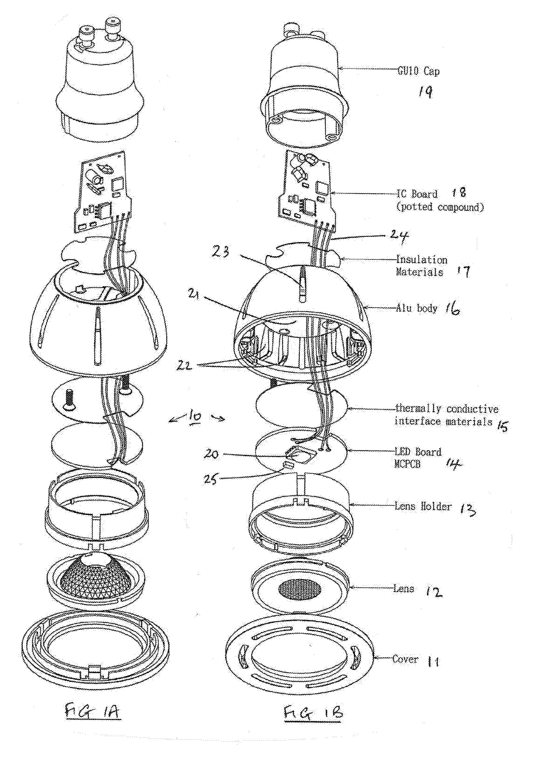
[0035]Referring to FIGS. 1A and 1B, these illustrate exploded diagram views of an LED lighting module according to the present invention. In this example the invention is expressed as a GU10 lamp 10. The lamp 10 comprises a GU10 cap 19, an aluminium lamp body16 which acts also as a heat sink, a lens holder 13, a lens 12 and a cover 11. These components are similar to those components found in an existing GU10 lamp. The arrangement and positioning of the LED module and the associated power management and power conversion, driver, dimming, control and sensing components within the LED lighting module set this invention apart from kn...


PUM


Abstract

An LED downlight lighting module is provided including an LED module having one or more single LEDs on a first printed circuit board, a heat sink, and a second printed circuit board. In an embodiment, the first printed circuit board is in good thermal contact with the heat sink such that heat from the LEDs is dissipated through the heat sink. In an embodiment, the second printed circuit board is adapted to accommodate a power and control circuitry for the LEDs, and is thermally insulated from the heat sink and from the first printed circuit board, and thus from the LED module. According to an aspect, the LEDs serve as the principal heat generating component on the printed circuit board, thus helping to increase the light output from the LEDs and / or increase the lifespan of the LED downlight lighting module.

Description

FIELD OF INVENTION[0001]The present invention relates to LED light engines, LED lamps and LED luminaires. It is particularly applicable to LED lamps and LED products containing an on board driver and / or on board control integrated circuits.BACKGROUND TO THE INVENTION[0002]LED luminaires and lamps are increasing in popularity and it is expected that this popularity will continue to increase in the future as their light output improves both quantitatively and qualitatively. With lighting units that include LED modules it is important to prevent overheating of the LED module, because overheating can seriously reduce the service life of the lighting element, resulting in premature failure of the LED lamp / luminaire.[0003]In many currently available LED lamps and luminaires one or more LED modules together with their associated driver(s) and other control components are mounted together on the same printed circuit board, generally a metal printed circuit board (MCPCB), often made of alumi...

Claims


Application Information

Patent Timeline
IPC IPC(8): F21V29/77F21S8/02F21V25/12F21V3/04F21V5/04F21V21/26F21V23/00F21V29/89H05B44/00
CPCF21V29/77F21V23/005F21S8/026F21V29/89F21V3/0418H05B37/0272F21V21/26F21V25/12F21Y2115/10H05B33/0845F21V5/04F21V29/507F21V23/009F21V19/003F21Y2101/00F21V29/83F21V29/773F21V29/713F21K9/233F21V23/006F21V3/061H05B45/10H05B47/19F21K9/23
Inventor JOHNSON, ANDREW
Owner GOOEE
Learn More