Light source system, and projection system and method

a light source system and projection system technology, applied in the field of optical equipment, can solve the problems of low conversion efficiency of red phosphors, low light efficiency and reliability of the system, and shortcomings in output image brightness and color gamut, so as to reduce color gamut, reduce output image brightness, and high efficiency

Active Publication Date: 2017-02-16
APPOTRONICS CORP LTD
View PDF11 Cites 10 Cited by
  • Summary
  • Abstract
  • Description
  • Claims
  • Application Information

AI Technical Summary

Benefits of technology

[0033]Conventional technologies use single DMD chip to simultaneously process the three primary color lights, or three DMD chips where each DMD processes a single primary color light. This way, the red, green and blue primary lights are input to the DMD in a time sequence to be modulated. The limitations of efficiency of red phosphors lower the output image brightness and reduces color gamut. In embodiments of the present invention, by exciting relatively high efficiency phosphors, a combined light containing two primary colors is generated, such as yellow light co

Problems solved by technology

However, in this technology which uses semiconductor laser devices to excite phosphor materials in the color wheel, red phosphors have low conversion efficiency, leading to shortcomings in output im

Method used


Image

  • Light source system, and projection system and method
  • Light source system, and projection system and method
  • Light source system, and projection system and method

Examples


first embodiment

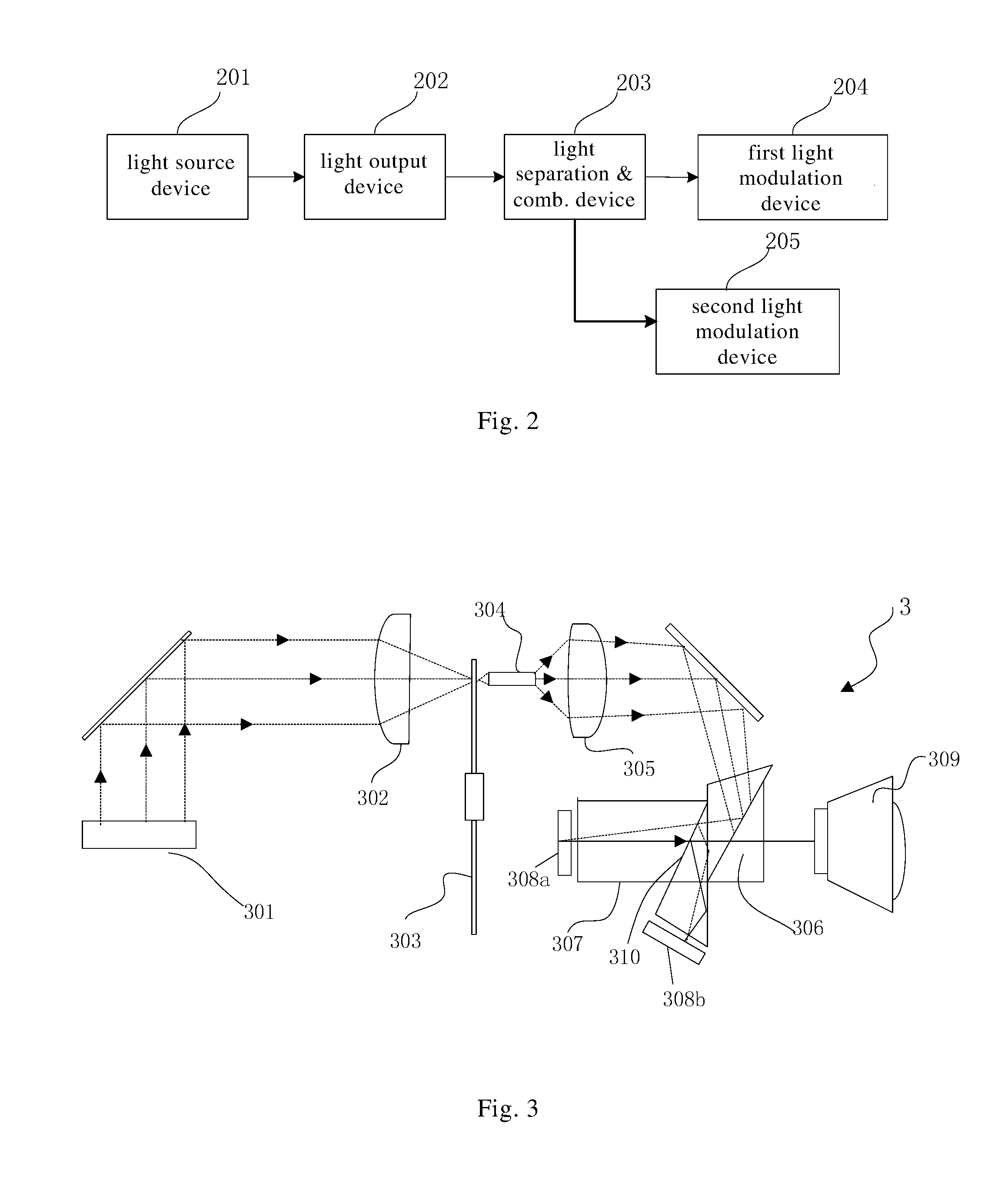
[0066]FIG. 2 schematically illustrates the structure of a light source system according to an embodiment of the present invention. As shown in FIG. 2, the light source system includes: light source device 201, light output device 202, light separation and combination device 203, first light modulation device 204 and second light modulation device 205. The light source device 201 is a laser light source that generates at least one group of excitation light. The light output device 202 receives the excitation light and converts the excitation light to generate a converted light for output. The light output device includes at least two different wavelength conversion materials, and at least one of the wavelength conversion materials generates a converted light that is a multi-color light. The light separation and combination device 203 separates the multi-color light into a first light of a first wavelength range travelling along a first light path and a second light of a second wavele...

second embodiment

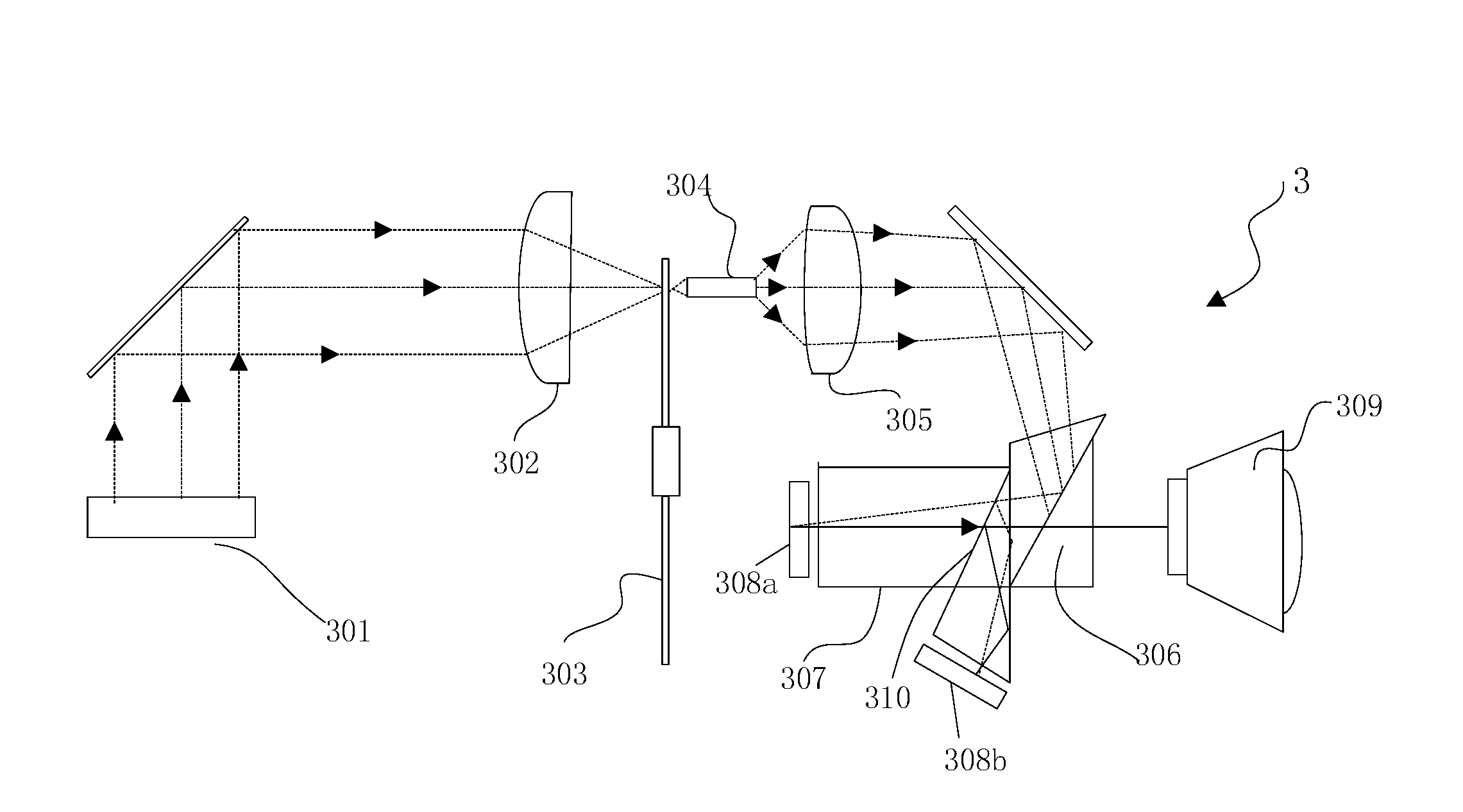
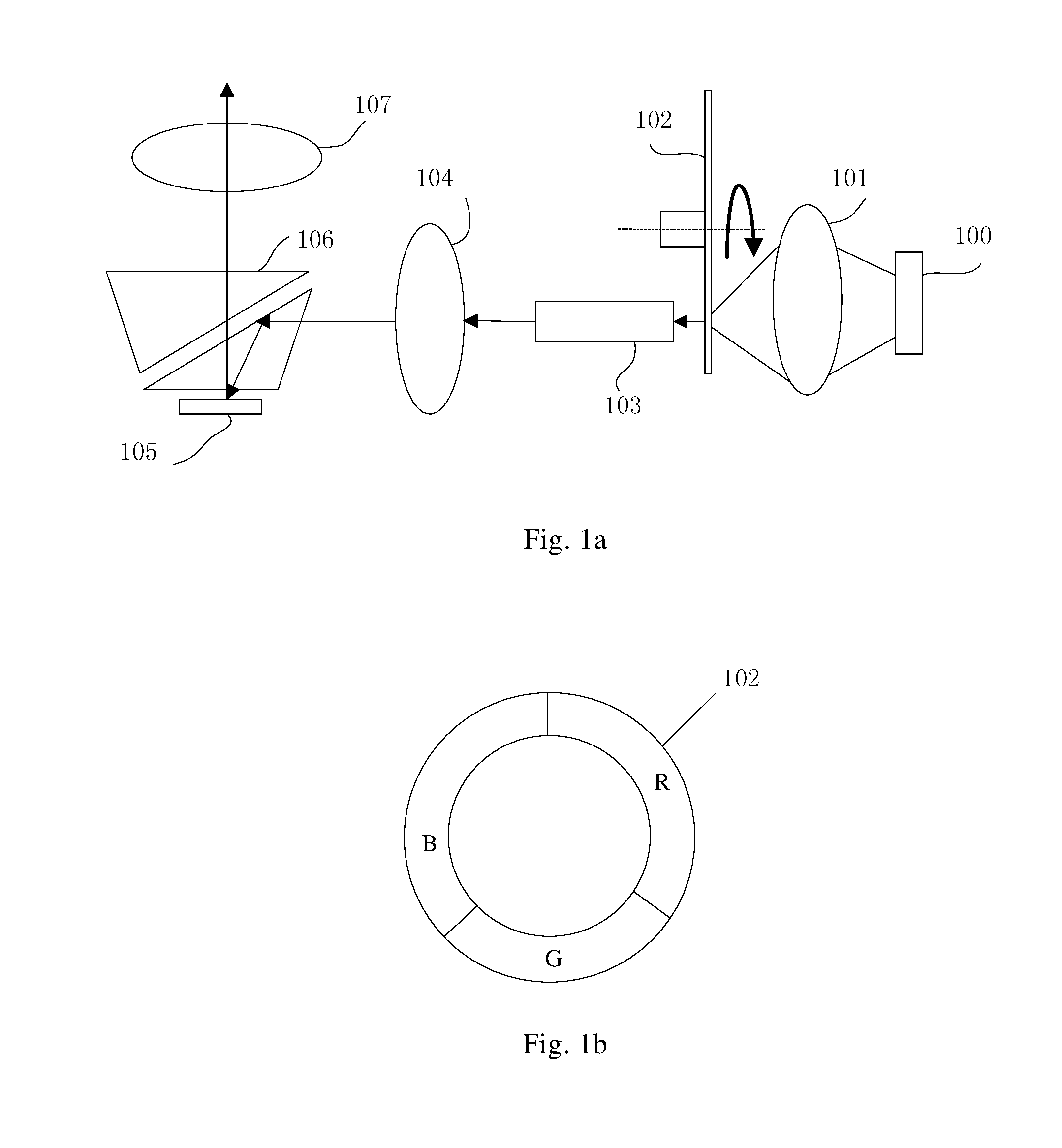
[0074]FIG. 3 schematically illustrates the structure of a projection system according to a preferred embodiment of the present invention. FIG. 4 shows a plan view of a light output device of the embodiment of FIG. 3. FIG. 5 is a timing diagram showing the blue and yellow light sequence outputted from the light output device. FIG. 6 illustrates the distribution of green and red lights after the light separation coating. FIG. 7a is a timing diagram of the reflected light from the first DMD. FIG. 7b is a timing diagram of the reflected light from the second DMD. As shown in FIGS. 3 to 7b, the projection system includes a light source system, which includes: light source device, light output device, light separation and combination device, first light modulation device and second light modulation device.

[0075]More specifically, the light source device includes: excitation light source (laser) 301, and collection lens 302. The light output device includes color wheel 303. The light separ...

third embodiment

[0078]FIG. 8 shows a plan view of an improved light output device of the projection system of the embodiment of FIG. 3. FIG. 9 is a timing diagram of the reflected light from the first DMD. FIG. 10 is a timing diagram of the reflected light from the second DMD. As shown in FIGS. 8, 9 and 10, compared to the second embodiment, this embodiment changes the color wheel of the second embodiment to a two-segment color wheel 303a which has a cyan segment and a yellow segment, with other components remaining unchanged. The color wheel 303a outputs a sequence of cyan light and yellow light, which is homogenized by the light rod 304, collimated by the optical relay system 305, and then inputted to the TR prism 306 and the light separation and combination prism 307. A light separation film 310 is coated between the two prisms of the light separation and combination prism 307. The light separation film 310 separates the yellow light in the input light into a red light and a green light, and sep...


PUM


Abstract

A light source system including: a light source device emitting excitation light; an light output device receiving the excitation light and converting it into converted light, wherein the light output device includes at least two different wavelength conversion materials, the converted light of at least one wavelength conversion material being a multi-color light; a light splitting and combining device splitting the multi-color light into a first and a second color light propagating respectively along a first and a second optical channel, wherein the first and second color lights have different wave spectrum coverage ranges; and a first and a second light modulation device respectively modulating the light propagating over the first and second optical channels, wherein the light of three primary colours can be allocated to two DMDs for processing. This results in improved colour gamut of the light source and the light efficiency and reliability of the system.

Description

BACKGROUND OF THE INVENTION[0001]Field of the Invention[0002]This invention relates to optical apparatus, and in particular, it relates to a light source system, projection system and related methods.[0003]Description of Related Art[0004]Digital light processing (DLP) projection technology is gaining wide use, a core piece of which is digital micro-mirror device (DMD).[0005]FIG. 1a illustrates a conventional single chip DMD projection system. As shown in FIG. 1, the system includes: excitation light source 100, collection lens 101, rotating color wheel 102, light rod 103, optical relay system 104, DMD chip 105, TIR (total internal reflection) prism 106, and projection lens 107. The excitation light source 100 is a semiconductor laser, and its emitted light is focused by the collection lens 101 onto the rotating color wheel 102. The rotating color wheel 102 is coated with wavelength conversion materials (e.g. phosphors) on different color segments. FIG. 1b is a plan view of the rotat...

Claims


Application Information

Patent Timeline
IPC IPC(8): H04N9/31G02B26/08G03B21/20F21V9/10G02B26/00F21V9/40
CPCH04N9/3114F21V9/10G02B26/0833G03B21/204G02B26/008F21V13/00F21V9/45G03B21/14G03B21/20H04N9/31
Inventor GUO, ZUQIANGWANG, ZEQIN
Owner APPOTRONICS CORP LTD
Why Eureka
Try Eureka