Mass production MTF testing machine

a mass production, testing machine technology, applied in the direction of measurement devices, instruments, television systems, etc., can solve the problems of lack of flexibility in testing different lenses with the same set-up, large arrangement, and high cost, and achieve the effect of increasing focal length and apertur

Inactive Publication Date: 2017-02-16
AHARON OREN
View PDF7 Cites 18 Cited by
  • Summary
  • Abstract
  • Description
  • Claims
  • Application Information

AI Technical Summary

Benefits of technology

[0012]Testing methods and systems suitable for testing lenses and cameras for mass production are described, using innovative mechanical mechanism for moving multiple telescopes or cameras or a combination of both, each telescope having a center of rotation position around the lens under test. Each of the respective telescopes has a significantly higher focal length and aperture relative to the tested lens and examines the projected image from lens under test to calculate its MTF value as a function of the angular movement. For camera testing, the preferred embodiment will be replacing the camera equ...

Problems solved by technology

Due to the relatively high telescopic camera dimensions, this arrangement tends to be massive and expensive—for some applications as many as 17 different t...

Method used


Image

  • Mass production MTF testing machine
  • Mass production MTF testing machine
  • Mass production MTF testing machine

Examples


Embodiment Construction

[0020]Several embodiments of the invention with reference to the appended drawings are now described. Other instances, well-known circuits, structures, and techniques have not been shown in detail so as not to obscure the understanding of this description.

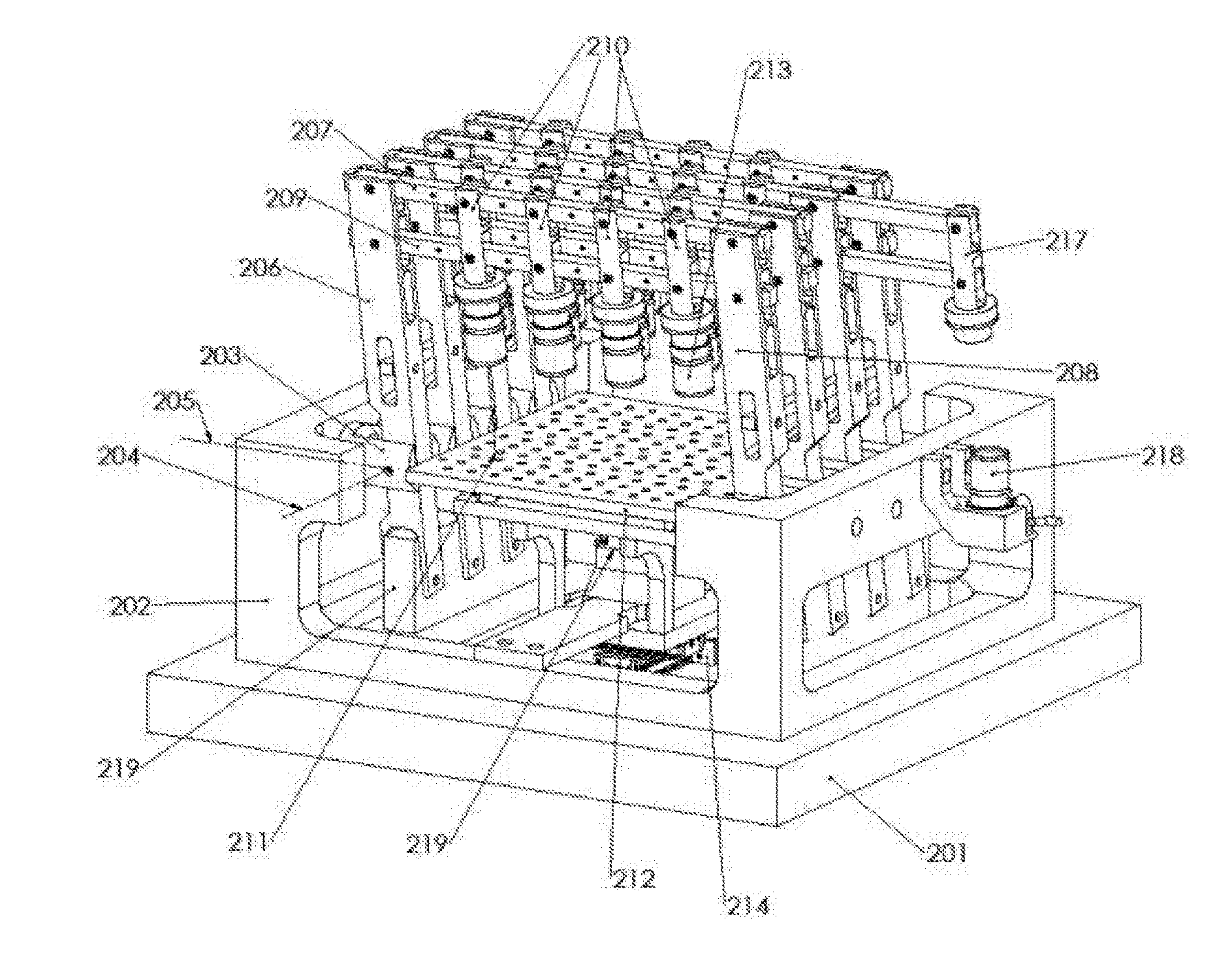
[0021]There are various defects that appear during the manufacturing of digital cameras. One serious defect (that can result in a camera specimen being rejected during manufacture testing) is related to lens performance—that why it is important to test each lens independently from its camera. Moreover, defects could be related to the camera full assembly where defects may be manifested as a drop in imagining quality of a test scene captured by a unit or device under test is displayed. A good manufacturing practice in this case is to test both lens and camera assembly which the disclosed art will do.

[0022]As shown in the disclosed figures, the testing procedure for camera lens includes an array of illuminated targets projecting a st...


PUM


Abstract

As the demand for higher quality and higher resolution optical systems has become prevalent, both designers and metrology scientists demand mass production test stations for optical elements. Consequently, this technology is expected to be standard procedure. Prior art's slow MTF measurement technique is expensive and inadequate for mass production. Current proposed art will solve this and other important drawbacks by simultaneously testing multiple cameras. The proposed parallel testing method will be fast and accurate while meeting the market requirements and fulfill the growing need.
This novel art will enable measuring MTF and other optical parameters in parallel formation within one test station.
The Modulation Transfer Function (MTF) is an important aid which is necessary for objective evaluation of the image-forming capability of optical systems. Not only that the MTF provides a means of expressing the imaging quality of optical systems objectively and quantitatively, but it can be calculated from the lens design data. Moreover, other parameters which are also very important, such as field of view, focal length and similar parameters can be measured by the proposed art.
This technology allows optical and systems designers to predict and test reliably the performance of the optical systems. The manufacturers can compare the image quality of the camera and lenses with the design expectations.
Thus a method and apparatus are disclosed for fast parallel testing of multiple lenses or cameras.
A unique electro optical design will be implemented to shift multiple optical elements in a synchronized matter while maintaining accuracy over a wide field of view. The movement is angular over a wide angle and in two perpendicular directions—pitch and yaw. By design, each said optical element will perform its angular movement around the lens under test from remote. The center of rotation will be the central point of each lens input aperture. The apparatus is suitable for testing both camera and lenses simultaneously. The apparatus will preferably test lenses or cameras directly on the production floor.

Description

BACKGROUND OF THE INVENTION[0001]1. Field of Invention[0002]The present invention is related to the field of MTF testing procedure of lenses or digital cameras used in mass production. Therefore, for this application, quality and high speed are the most important parameters. More specifically, the invention is related to the utilization of an innovative device capable of measuring a tray loaded with multiple elements. Measurement is simultaneously performed by using multiple telescopes or collimators shifted in parallel while each collimator or telescope rotates and projects its image to the center of each lens under test. Other relevant measurements are focal length, focusing position field of view and other optical parameters. One advantage of the presented innovations is the mechanical arrangement enabling parallel collimators or telescopic cameras movement where each device is rotating around the center of each lens under test from remote. By irradiating from multiple points aro...

Claims


Application Information

Patent Timeline
IPC IPC(8): H04N17/00G01B11/27G01M11/02
CPCH04N17/002G01B11/272G01M11/0214G01M11/0207G01M11/0257
Inventor AHARON, OREN
Owner AHARON OREN
Why Eureka
Try Eureka