Method and apparatus for adjusting installation flatness of lens in real time

a technology of installation flatness and real-time adjustment, which is applied in the field of real-time adjustment of installation flatness of lenses, can solve the problems of limited display and printing devices, limited devices, and unsuitable for the wide automatic industrial production, and achieves flexibly adjustable and robust effect, saving manpower and physical resources

Active Publication Date: 2017-02-16
SZ DJI TECH CO LTD
View PDF8 Cites 3 Cited by
  • Summary
  • Abstract
  • Description
  • Claims
  • Application Information

AI Technical Summary

Benefits of technology

[0025]The present disclosure has the following benefits: the present disclosure acquires an image of a testing chart captured by a camera in real time, where the image comprises at least two groups of testing charts regarding different positions of a camera photosensitive surface; pre-processes the image to obtain each group of testing charts by separation; calculates and displays, based on each group of testing charts, a real-time resolution value of the camera photosensitive surface to each group of testing charts in real time; and adjusts the installation angle of the optical axis of the camera lens relative to the camera photosensitive surface in real time based on the real-time resolution value of the camera photosensitive surface to each group of testing charts. In this way, a real-time resolution value of a camera can be obtained in real-time and automatically, and the installation angle of the optical axis of the camera relative to a camera photosensitive surface can be adjusted in real time based on the real-time resolution value of the camera, thus saving the manpower and physical resources. In addition, the measurement result thereof matches that of the visual evaluation method, and is flexibly adjustable and robust.

Problems solved by technology

Although the visual evaluation method is simple, it has shortcomings of being liable to influence of individual differences, time and labor consuming, and limited by the displaying and printing devices.
The visual evaluation method is simple to operate but is limited by the devices and consumes labor, so it is unsuitable for the wide automatic industrial production.
The MTF-based measurement method (e.g., the HYRes software from Japan) has long been proved to be effective, but with the advent of digital cameras of the 10-million pixel scale, the capturing resolution has already exceeded the limits of USAF1951 and ISO12233, which makes the MTF-based measurement method unable to test such digital cameras.
Meanwhile, the MTF-based measurement method is computation intensive, and does not allow for real-time dynamic processing.
The SFR-based measurement method (e.g., the Imatest software from the U.S.) has a low cost and provides a good drawing effect, but it is complex to operate, demands higher skills of the testing personnel, and does not allow for real-time dynamic testing.

Method used


Image

  • Method and apparatus for adjusting installation flatness of lens in real time
  • Method and apparatus for adjusting installation flatness of lens in real time
  • Method and apparatus for adjusting installation flatness of lens in real time

Examples


Embodiment Construction

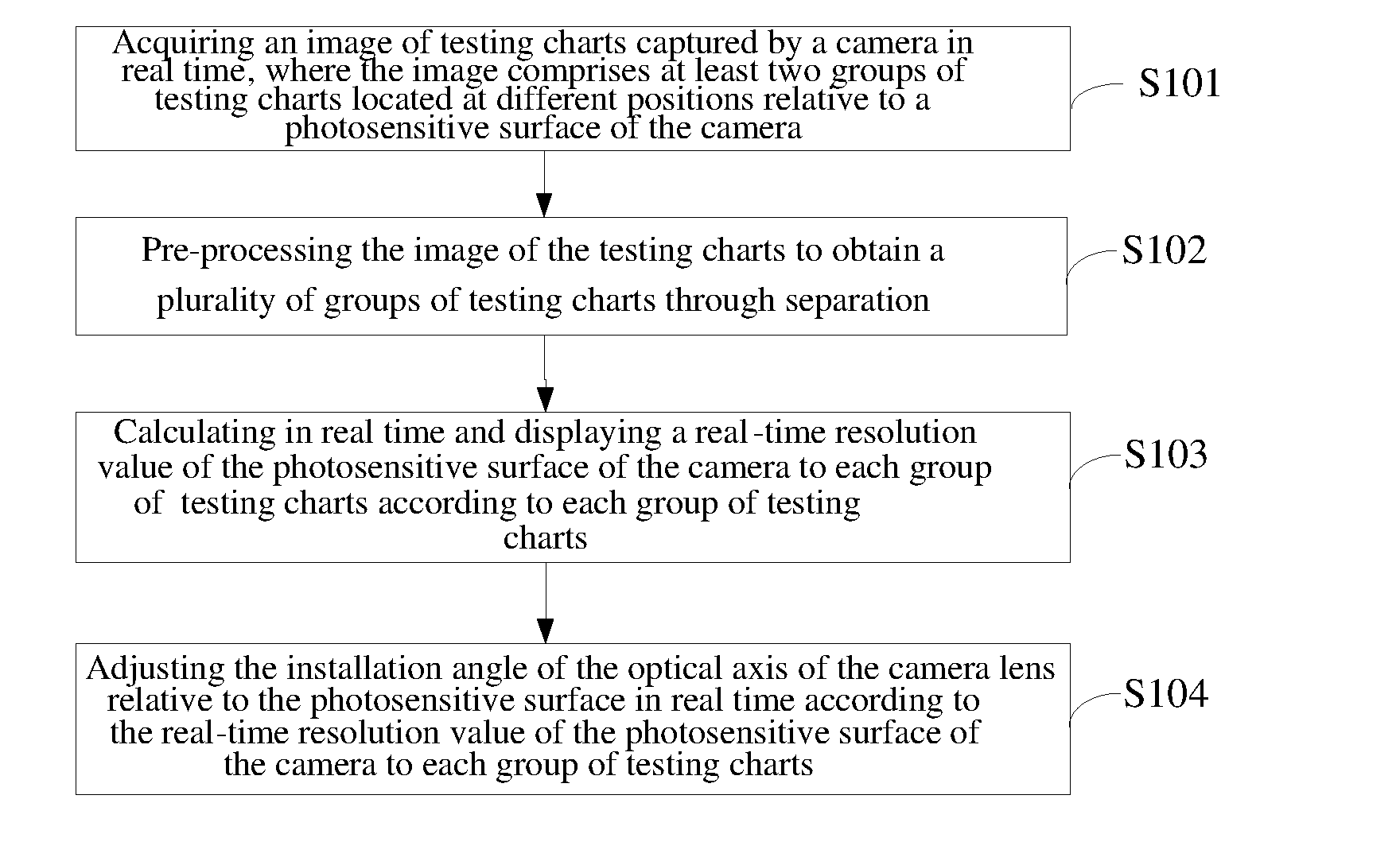
[0043]Referring to FIG. 1, FIG. 1 shows a flowchart illustrating a method for adjusting installation flatness of a lens in real time according to an embodiment of the present disclosure. This embodiment is described from the perspective of an apparatus for adjusting the installation flatness of a lens in real time. The method for adjusting the installation flatness of the lens in real time of this embodiment comprises:

[0044]S101: acquiring an image of a testing chart captured by a camera in real time, wherein the image comprises at least two groups of testing charts regarding different positions of a camera photosensitive surface.

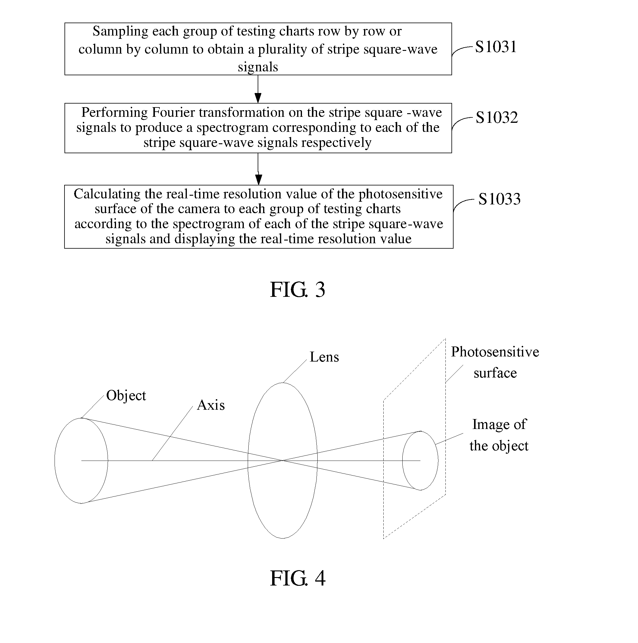
[0045]Refer to FIG. 4, FIG. 4 shows a schematic view illustrating an imaging principle of a camera. Light rays coming from an object pass through a lens of a camera and then converge onto a film to form an inverted and downsized real image. The optical axis of the camera lens runs through the center points of the object, the lens, and the image of the objec...


PUM


Abstract

A method and an apparatus for adjusting installation flatness of a lens in real time are provided. The method comprises: acquiring an image captured by a camera in real time, where the image comprises at least two groups of testing charts regarding different positions; pre-processing the image to obtain each group of testing charts by separation; calculating and displaying, based on each group of testing charts, a real-time resolution value of a camera photosensitive surface to each group of testing charts in real time; and adjusting the installation angle of the optical axis of the camera lens relative to the camera photosensitive surface in real time based on the real-time resolution value of the camera photosensitive surface to each group of testing charts.

Description

FIELD OF THE INVENTION[0001]The present disclosure relates to a method and an apparatus for adjusting installation flatness of a lens in real time.BACKGROUND OF THE INVENTION[0002]Resolution measurement of a digital camera is usually accomplished by capturing an ISO chart, printing or displaying the captured image, and then visually evaluating the image in a subjective way to obtain a visually measured resolution value or using a software measurement method consistent with the visual evaluation method to evaluate image to acquire the resolution value.[0003]In the visual evaluation method by visual inspection, an ISO pattern is printed or magnified by a fixed factor to observe a spatial frequency at which wedge-shaped lines vary, and the spatial frequency is taken as the resolution. Although the visual evaluation method is simple, it has shortcomings of being liable to influence of individual differences, time and labor consuming, and limited by the displaying and printing devices. T...

Claims


Application Information

Patent Timeline
Patent Type & Authority Applications(United States)
IPC IPC(8): H04N17/00G03B43/00G02B27/62H04N5/225
CPCH04N17/002G02B27/62G03B43/00H04N5/2254
Inventor JIANG, CAIGAOCAO, ZISHENGWANG, MINGYULIANG, TAIWENTANG, XIAOZHENG
Owner SZ DJI TECH CO LTD
Why Eureka
Try Eureka