Check patentability & draft patents in minutes with Patsnap Eureka AI!

Method and System for Coding Signals using Distributed Coding and Non-Monotonic Quantization

a distributed coding and quantization technology, applied in the field of signal processing, can solve the problems of lossy compression, complex encoders produced by encoding techniques, and the need for very simple decoders

Active Publication Date: 2017-02-16
MITSUBISHI ELECTRIC RES LAB INC
View PDF4 Cites 3 Cited by
  • Summary
  • Abstract
  • Description
  • Claims
  • Application Information

AI Technical Summary

Benefits of technology

The patent describes a decoder and method for estimating encoded values in a multi-dimensional space. The decoder includes a memory that stores a map of the encoded values, which consists of cells that enclose clusters of values and quantize them. Each cell is labeled with a unique label that does not share a common border. The decoder also has a receiver to receive the label of a cell that encloses the transmitted encoded value, and a processor to estimate the encoded value and select the closest cell to the estimate on the map. The method described in the patent uses side information to improve the accuracy of the estimate. The technical effects of this patent include improved accuracy and efficiency in estimating encoded values in a multi-dimensional space.

Problems solved by technology

In such applications, the goal is to encode the signal with an encoder and use a small number of bits to represent the signal, such that the signal can be transmitted at a lower bit rate, at the expense of some distortion in the signal, i.e., there is some loss of information duting the compression, hence the compressions is lossy.
Unfortunately, those encoding techniques produce very complex encoders, and, typically require very simple decoders.
There, the encoder has significant resources available, while the decoder, at the playback device, has limited resources.
However, in applications in which the encoder has to be limited computationally, this becomes problematic.
For example, the computational resources available for satellite image or radar signal compression is very limited due to restrictions on the processors and power that can withstand space travel conditions.
Similarly, in applications, such as hyperspectral or multispectral image compression, the amount of data that need to be used for prediction and transformation require memory storage prohibitive for the state of the art portable devices.
For many of such applications, the computational resources and power available to the decoder are essentially unlimited.
This class of methods does not perform the prediction step at the encoder.
Because the prediction is based on the side information, it can be imperfect, and, therefore, the decoding can incur significant distortion.
On the other hand, the decoder complexity increases significantly, making compression with side information applicable when the decoder can be a more powerful system than the encoder.
Although compression with side information reduces the load at the encoder, it still requires the transformation step in addition to the encoding step, which, in some cases, can be computationally complex.
If the methods fail to transmit sufficient error correcting information, then the decoding can fail and recover a signal that is unrelated to the original signal.
In many cases, failure in the error correction might result to a bitstream that cannot be decoded.
For this reason, most practical methods transmit a larger number of syndrome bits than necessary, to guarantee the correction works, thus wasting bandwidth.
In addition, the extra bits do not improve the distortion performance of the compression method.
This requires both real-time decoding and two-way communication between the encoder and the decoder, which is not possible in many applications.

Method used


Image

  • Method and System for Coding Signals using Distributed Coding and Non-Monotonic Quantization
  • Method and System for Coding Signals using Distributed Coding and Non-Monotonic Quantization
  • Method and System for Coding Signals using Distributed Coding and Non-Monotonic Quantization

Examples


Embodiment Construction

[0037]Non-Monotonic Quantization for Compression with Side Information

[0038]Compression Method and System

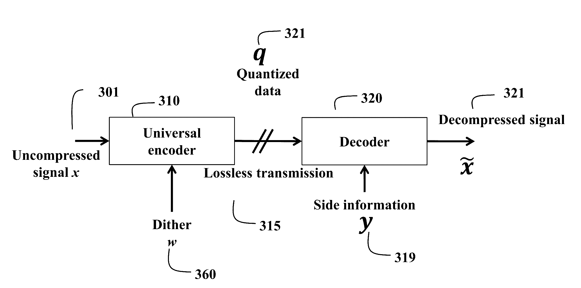
[0039]FIG. 1C shows a method and system for compressing according to some embodiments of the invention. The system includes an encoder 310 that takes an uncompressed signal 301 as input to produce quantized measurements 321, which can be transmitted losslessly 315 to a decoder 320. The decoder decodes the quantized measurements using side information y 319 to produce a decompressed signal 321.

[0040]Overview

[0041]Encoder

[0042]The role of the universal encoder is to encode the signal x 301 to a bitstream that is the compressed signal 321. The encoder assumes that the decoder is able to use the side information y 319 form a prediction of x, denoted {circumflex over (x)}, which can include some distortion.

[0043]To encode the uncompressed x, the encoder 310 obtains linear measurements of x, to which dither w 360 is added, and then quantized using non-monotonic quantization to produce ...


PUM


Abstract

A decoder includes a memory storing a map of a space of encoded values. The map includes a plurality of cells partitioning the space, such that each cell encloses a cluster of encoded values and quantizes the cluster of encoded values to a quantized encoded value. Each cell is identified by a label selected from a finite alphabet, such that multiple cells in the map are identified by the same label, and the cells are labeled such that a pair of cells identified by the same label does not share a common boarder. The decoder also includes a receiver to receive from an encoder a label of a cell enclosing an encoded value on the map of the space and a processor to estimate the encoded value using side information to produce an estimation of the encoded value, to select a cell identified by the received label on the map of the multi-dimensional space that is the closest to the estimation of encoded value, and to determine the encoded value as the quantized encoded value of the selected cell.

Description

RELATED APPLICATION[0001]This application is a continuation-in-part of U.S. application Ser. No. 14 / 822,212, “Method and System for Coding Signals using Distributed Coding and Non-Monotonic Quantization,” Boufounos et al., filed Aug. 10, 2015.FIELD OF THE INVENTION[0002]This invention relates generally to signal processing, and more particularly to coding uncompressed signals, wherein the coding includes encoding and / or decoding.BACKGROUND OF THE INVENTION[0003]Lossy compression is widely used in signal processing and signal transmission. There are several applications of lossy signal compression, such as the compression of camera images, multispectral images, hyperspectral images, and synthetic aperture radar (SAR) data, to name a few. In such applications, the goal is to encode the signal with an encoder and use a small number of bits to represent the signal, such that the signal can be transmitted at a lower bit rate, at the expense of some distortion in the signal, i.e., there i...

Claims


Application Information

Patent Timeline
IPC IPC(8): H04N19/50G01S13/90H04N19/126
CPCH04N19/50G01S13/90H04N19/126H04N19/124H04N19/395G06T1/0007G06T2207/10036G06T2207/10044
Inventor BOUFOUNOS, PETROSVALSESIA, DIEGO
Owner MITSUBISHI ELECTRIC RES LAB INC
Features
  • R&D
  • Intellectual Property
  • Life Sciences
  • Materials
  • Tech Scout
  • Unparalleled Data Quality
  • Higher Quality Content
  • 60% Fewer Hallucinations
Learn More