Liquid crystal composition and liquid crystal display device

Inactive Publication Date: 2017-02-23
JNC CORP +1
View PDF20 Cites 2 Cited by
  • Summary
  • Abstract
  • Description
  • Claims
  • Application Information

AI Technical Summary

Benefits of technology

[0016]An advantage of the invention is a liquid crystal composition satisfying at least one of characteristics such as a high maximum temperature of a nematic phase, a low minimum temperature of the nematic phase, a large optical anisotropy, a large positive dielectric anisotropy and a high stability to ultraviolet light. Another advantage is a liquid crystal composition having a suitable balance regarding at least two of the c

Problems solved by technology

A large dielectric anisotropy in the composition contributes to a low threshold voltage, a small electric power consumpt

Method used


Image

  • Liquid crystal composition and liquid crystal display device
  • Liquid crystal composition and liquid crystal display device
  • Liquid crystal composition and liquid crystal display device

Examples


Example

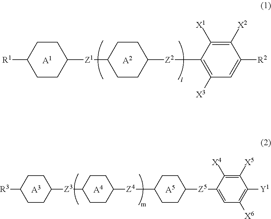
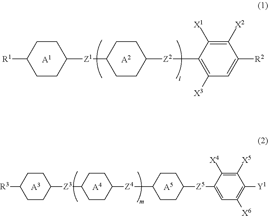
[0045]Composition B consists essentially of liquid crystal compounds selected from compound (1), compound (2) and compound (3) An expression “essentially” means that the composition may contain the additive, but contains no any other liquid crystal compound. Composition B has a smaller number of components than composition A has. Composition B is preferred to composition A in view of cost reduction. Composition A is preferred to composition B in view of possibility of further adjusting the characteristics by mixing any other liquid crystal compound.

[0046]Second, the main characteristics of the component compounds and the main effects of the compounds on the characteristics of the composition will be described. The main characteristics of the component compounds are summarized in Table 2 on the basis of advantageous effects of the invention. In Table 2, a symbol L stands for “large” or “high,” a symbol M stands for “medium” and a symbol S stands for “small” or “low.” The symbols L, M...

Example

Example 1

[0108]

3-HB(F)TB-2(1-1-3)5%3-HB(F)TB-3(1-1-3)5%3-HB(F)TB-4(1-1-3)5%3-H2BTB-2(1-1-5)3%3-H2BTB-3(1-1-5)3%3-H2BTB-4(1-1-5)3%3-BB(F,F)XB(F,F)-F(2-1-2)9%3-BB(F)B(F,F)XB(F)-F(2-1-5)3%3-BB(F)B(F,F)XB(F,F)-F(2-1-6)2%4-BB(F)B(F,F)XB(F,F)-F(2-1-6)7%5-BB(F)B(F,F)XB(F,F)-F(2-1-6)7%3-BB(F,F)XB(F)B(F,F)-F(2-1-10)6%3-BB(F)B(F,F)-F(2-2-4)3%2-BTB-O1(3-3)7.8% 3-BTB-O1(3-3)7.8% 4-BTB-O1(3-3)7.8% 4-BTB-O2(3-3)7.8% 5-BTB-O1(3-3)7.8% 

[0109]NI=90.0° C.; Tc<−20° C.; Δn=0.246; Δ∈=9.4; Vth=1.88 V; η=42.7 mPa·s; γ1=279 mPa·s; VHR-1=98.7%; VHR-3=97.0%.

Example

Comparative Example 1

[0110]The composition in Example 1 contains compound (2) being the second component. Compound (2) has a positive dielectric anisotropy. For comparison, a composition in which all of compounds (2) in Example 1 were removed, and a compound having a positive dielectric anisotropy and a cyano group was added was taken as Comparative Example 1.

3-HB(F)TB-2(1-1-3)7%3-HB(F)TB-3(1-1-3)7%3-HB(F)TB-4(1-1-3)7%3-H2BTB-2(1-1-5)5%3-H2BTB-3(1-1-5)4%3-H2BTB-4(1-1-5)4%2-BTB-O1(3-3)8.6% 3-BTB-O1(3-3)8.6% 4-BTB-O1(3-3)8.6% 4-BTB-O2(3-3)8.6% 5-BTB-O1(3-3)8.6% 1V2-BEB(F,F)-C11% 2-BEB(F)-C3%3-BEB(F)-C3%2-HHB-C3%3-HHB-C3%

[0111]NI=93.7° C.; Tc<−20° C.; Δn=0.242; Δ∈=10.0; Vth=1.82 V; η=32.3 mPa·s; γ1=264 mPa·s; VHR-1=97.5%; VHR-3=10.6%.

[0112]VHR of the compound having the cyano group is significantly decreased after irradiated with ultraviolet light, and therefore the compound is found to be unsuitable as a liquid crystal composition of the invention.


PUM

PropertyMeasurementUnit
Temperatureaaaaaaaaaa
Percent by massaaaaaaaaaa

Abstract

A liquid crystal composition satisfying at least one of characteristics such as high maximum temperature of a nematic phase, low minimum temperature thereof, large optical anisotropy, large positive dielectric anisotropy and high stability to ultraviolet light, or having suitable balance regarding at least two of the characteristics; and a liquid crystal display device including such a composition and particularly including an encapsulated composition, and a liquid crystal display device serving as a constituent of a display device that allows switching of display between 2D and 3D. The liquid crystal composition contains a specific compound having large optical anisotropy as a first component and a specific compound having large positive dielectric anisotropy as a second component, and may further contain a specific compound having large optical anisotropy and further having high maximum temperature or low minimum temperature as a third component, and the liquid crystal display device includes the composition.

Description

TECHNICAL FIELD[0001]The invention relates to a liquid crystal composition, a liquid crystal display device including the composition, and so forth. In particular, the invention relates to a liquid crystal composition having a large optical anisotropy and a large positive dielectric anisotropy, and a device including the composition.BACKGROUND ART[0002]In a liquid crystal display device, a classification based on an operating mode for liquid crystal molecules includes a phase change (PC) mode, a twisted nematic (TN) mode, a super twisted nematic (STN) mode, an electrically controlled birefringence (ECB) mode, an optically compensated bend (OCB) mode, an in-plane switching (IPS) mode, a vertical alignment (VA) mode, a fringe field switching (FFS) mode, and a field-induced photo-reactive alignment (FPA) mode. A classification based on a driving mode in the device includes a passive matrix (PM) and an active matrix (AM). The PM is classified into static, multiplex and so forth, and the...

Claims


Application Information

Patent Timeline
IPC IPC(8): C09K19/34C09K19/20C09K19/02C09K19/30
CPCC09K19/3402C09K19/3001C09K19/3003C09K19/3059C09K19/20G02F1/1334C09K2019/3016C09K2019/3063C09K2019/3422C09K2019/3009G02F1/134363C09K19/0208C09K19/14C09K19/18C09K19/42C09K2019/0466C09K2019/123C09K2019/181C09K2019/183C09K2019/188C09K2019/3025C09K2019/3051C09K19/12C09K19/30C09K19/34G02F1/13G02F1/1396G02B30/00
Inventor OKABE, EIJI
Owner JNC CORP
Why Eureka
Try Eureka