Aircraft turbine engine with improved mechanical power takeoff

a technology of mechanical power takeoff and turbine engine, which is applied in the direction of machines/engines, mechanical equipment, sustainable transportation, etc., can solve the problems of inability to meet the requirements remain in the field of mechanical power takeo

Active Publication Date: 2017-02-23
SN DETUDE & DE CONSTR DE MOTEURS DAVIATION S N E C M A
View PDF10 Cites 12 Cited by
  • Summary
  • Abstract
  • Description
  • Claims
  • Application Information

AI Technical Summary

Benefits of technology

[0010]With this arrangement specific to the invention, in particular in the case of breakdown on the turbine engine, the reliability of the mechanical power takeoff by the dedicated box is increased, since the whole of the low-pressure body is able to continue to rotate by autorotation effect of the fan. This reliability is all the more increased since the takeoff takes place on the driving element of this autorotation, that is to say the fan. This is particularly advantageous for responding to a vital requirement for lubrication of the reduction gear, even after a breakdown that has occurred on the turbine engine.
[0011]Moreover, it has been revealed that such a mechanical power takeoff led to higher global performances than those obtained in the conventional power takeoff solutions on the high-pressure shaft. In this regard, on such turbine engines with a reduction gear, savings in fuel ranging up to 4% have been recorded. This is partly explained by a lower power takeoff on the high-pressure body, which moreover makes it possible to reduce the dimensions thereof.
[0012]In addition, it is noted that the presence of a reduction gear in the low-pressure body, for driving the fan, is generally adopted for obtaining a high dilution ratio, typically greater than ten. For the record, the dilution ratio is the ratio of the mass of air passing through the fan to the mass of air used in the combustion chamber. The presence of a reduction gear allows an increase in the diameter of the fan and therefore promotes the obtaining of a higher dilution ratio, giving rise to better efficiency. Increasing this dilution ratio is also dependent on the use of a high-pressure body with smaller and smaller dimensions in comparison with the dimensions of the fan, which makes any mechanical power takeoff on the high-pressure shaft tricky. By taking off the power on the low-pressure body, and in particular on the fan, the invention consequently affords a satisfactory response to the difficulties encountered in the solutions of the prior art, with a takeoff on the high-pressure body.
[0013]In the particular case of the problem of lubrication of the reduction gear, it is noted that taking off mechanical power on the fan makes it possible to install compact lubrication means, propitious to a reduced overall space requirement. This is because these lubrication means no longer need to be oversized as in the solutions of the prior art, in which the takeoff took place on the high-pressure body, able to provide only a limited power in the case of breakdown. Naturally, this finding can be made for other types of equipment of the turbine engine, not only for the means for lubricating the reduction gear driving the fan.
[0022]The reduction gear is of the plain bearing type. For the record, plain bearings function like rolling bearings but the advantage lies in the fact that the rolling bodies are advantageously replaced by a film of oil. The result is an appreciable saving in terms of size. However, plain bearings do not withstand the degradation of the film of oil, which must always be present and have a certain speed (for hydrodynamic plain bearings), or a certain pressure (for hydrostatic plain bearings). During any autorotation phase of the fan, the design of the invention allows vital lubrication of these bearings by means of the takeoff made on the first toothed wheel, constrained to rotate with the fan. This principle is also valid on the ground, when the fan begins to rotate and the reduction gear must be lubricated.

Problems solved by technology

Nevertheless, in particular in the case of breakdown, it may happen that mechanical power takeoff requirements remain without being able to be produced by the high-pressure body that is weakly driven or no longer rotating.

Method used


Image

  • Aircraft turbine engine with improved mechanical power takeoff
  • Aircraft turbine engine with improved mechanical power takeoff
  • Aircraft turbine engine with improved mechanical power takeoff

Examples


Embodiment Construction

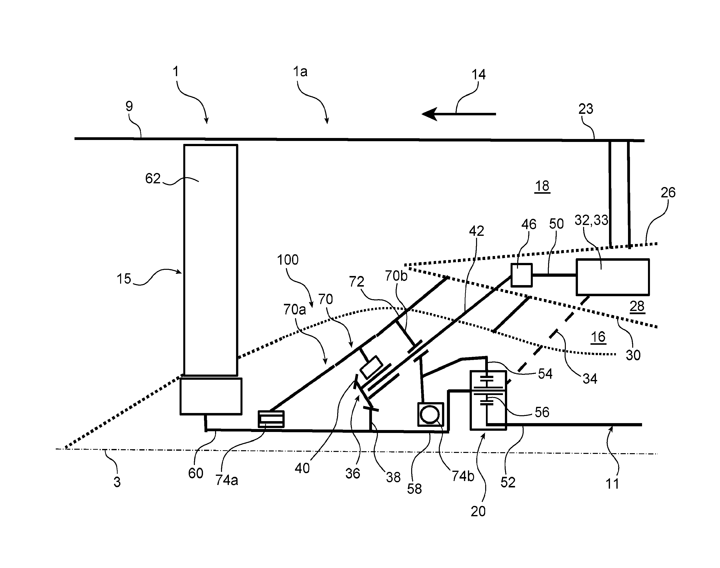
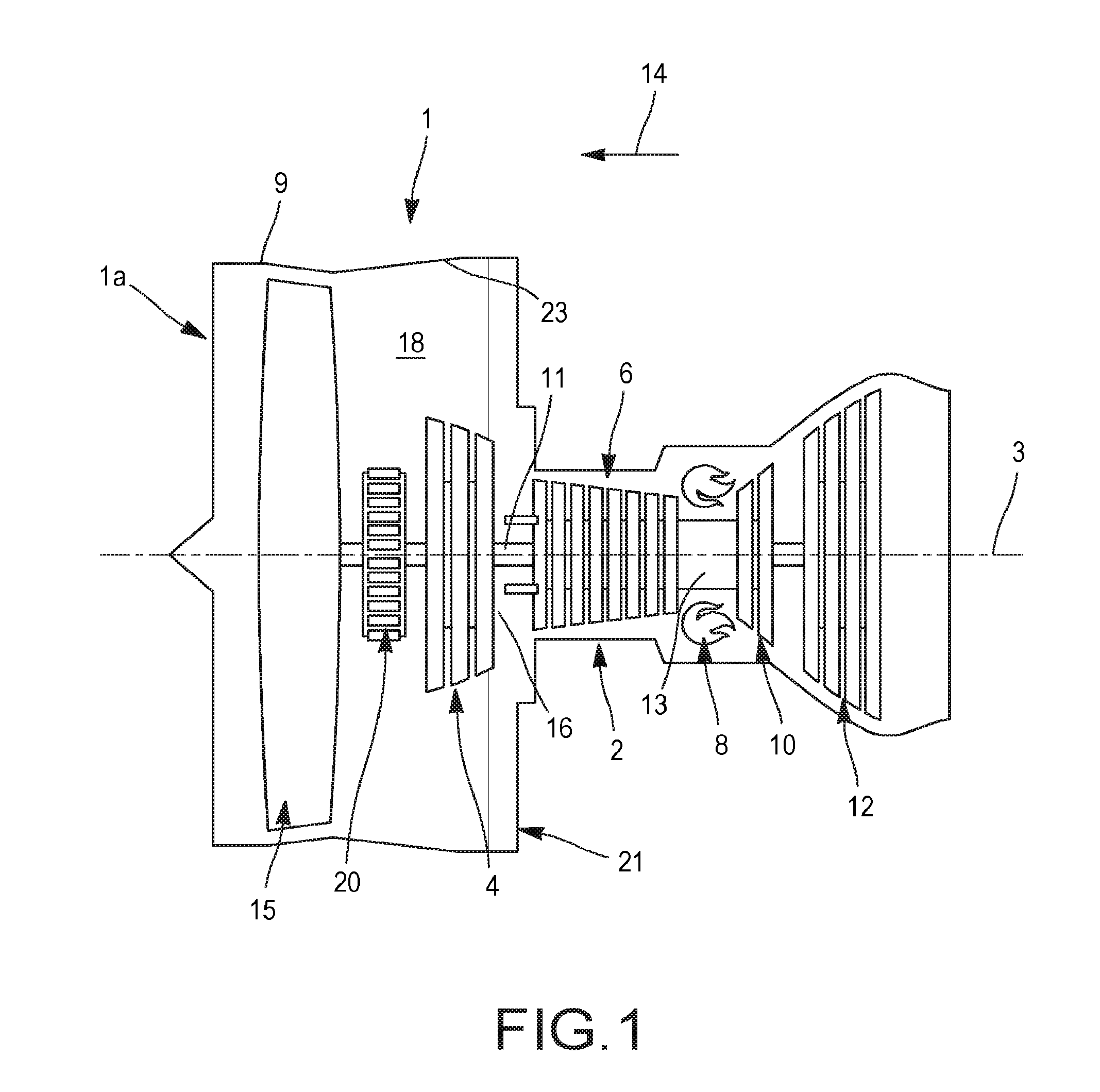
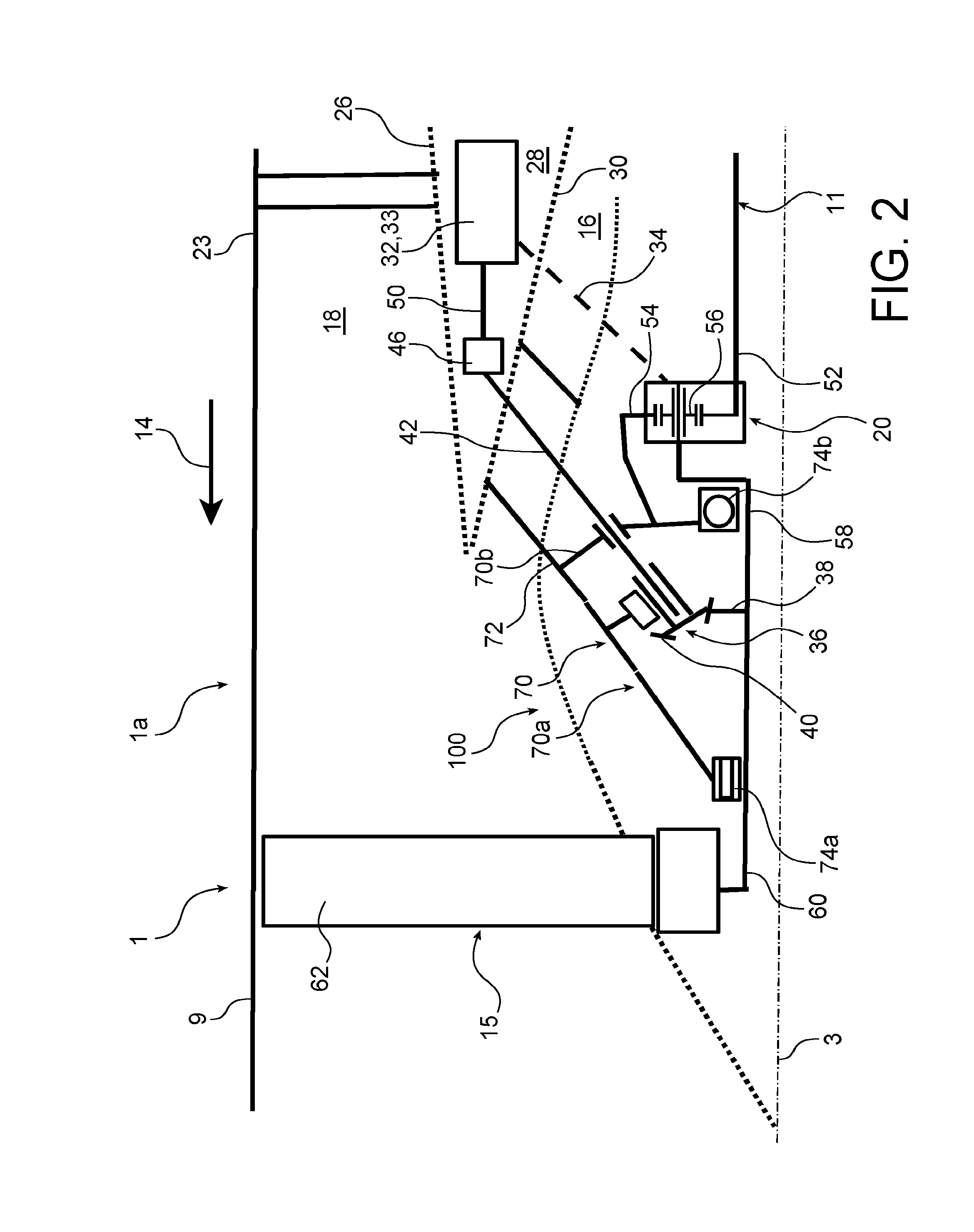
[0032]With reference first of all to FIGS. 1 and 2, a double-body bypass turbojet engine 1 is shown, having a high dilution ratio. The turbojet engine 1, which has a front part referenced 1a in FIG. 2, comprises in a conventional fashion a gas generator 2 on either side of which are arranged a low-pressure compressor 4 and a low-pressure turbine 12, this gas generator 2 comprising a high-pressure compressor 6, a combustion chamber 8 and a high-pressure turbine 10. Hereinafter the terms “front” and “rear” are considered in a direction 14 opposite to the main direction of flow of the gases in the turbojet engine, this direction 14 being parallel to the longitudinal axis 3 of said direction.

[0033]The low-pressure compressor 4 and the low-pressure turbine 12 form a low-pressure body and are connected to each other by a low-pressure shaft 11 centred on the axis 3. Likewise, the high-pressure compressor 6 and the high-pressure turbine 10 form a high-pressure body and are connected to each...


PUM


Abstract

An aircraft turbine engine includes a fan and a reduction gear including a plurality of rotary elements and driving the fan. The turbine engine further includes a gearbox and a mechanical power takeoff box driving the gearbox. The turbine engine includes a first toothed wheel and a second toothed wheel forming part of the mechanical power takeoff box and meshing with the first toothed wheel.

Description

TECHNICAL FIELD[0001]The present invention relates to the field of aircraft turbine engines comprising a mechanical power takeoff housing, also referred to as an “IGB” (inner gearbox) housing.[0002]The invention applies particularly to bypass turbojet engines, the fan of which is driven by a gearbox.PRIOR ART[0003]On existing turbine engines comprising a gearbox for driving the fan surrounded by a fan casing, taking off mechanical power on the high-pressure drive shaft is known, for driving a gearbox. The latter, also referred to as an “AGB” (accessory gear box), is for example housed in an inter-duct compartment of the turbine engine, that is to say a compartment situated radially between the primary channel and the secondary channel of the turbine engine.[0004]Such a gearbox is conventionally formed by means of shafts carrying spur gears for rotating one another, and for driving the equipment with which they are associated. By way of indicative example, the equipment may be of the...

Claims


Application Information

Patent Timeline
Patent Type & Authority Applications(United States)
IPC IPC(8): F02C7/06F02K3/06F02C7/36
CPCF02C7/06F02C7/36F05D2260/98F05D2260/40311F02K3/06F02C7/32F05D2240/90F05D2260/4031F01D25/162F05D2230/60F05D2240/53F05D2230/70Y02T50/60
Inventor NOWAKOWSKI, NATHALIEVINCENT, THOMAS ALAIN CHRISTIAN
Owner SN DETUDE & DE CONSTR DE MOTEURS DAVIATION S N E C M A
Why Eureka
Try Eureka