Scroll type device incorporating spinning or co-rotating scrolls

a scroll compressor and scroll technology, applied in the direction of machines/engines, rotary/oscillating piston pump components, liquid fuel engines, etc., can solve the problems of relatively large scroll devices, limited to a single stage of compression, and orbiting scroll compressors are typically limited in their maximum speed to under 4000 rpm, so as to reduce the axial load

Active Publication Date: 2017-02-23
AIR SQUARED
View PDF5 Cites 19 Cited by
  • Summary
  • Abstract
  • Description
  • Claims
  • Application Information

AI Technical Summary

Benefits of technology

[0018]The present disclosure is directed to a co-rotating scroll device that...

Problems solved by technology

In general, they have been limited to a single stage of compression due to the complexity of two or more stages.
Orbiting type scroll compressors are typically limited in their maximum sp...

Method used


Image

  • Scroll type device incorporating spinning or co-rotating scrolls
  • Scroll type device incorporating spinning or co-rotating scrolls
  • Scroll type device incorporating spinning or co-rotating scrolls

Examples


Embodiment Construction

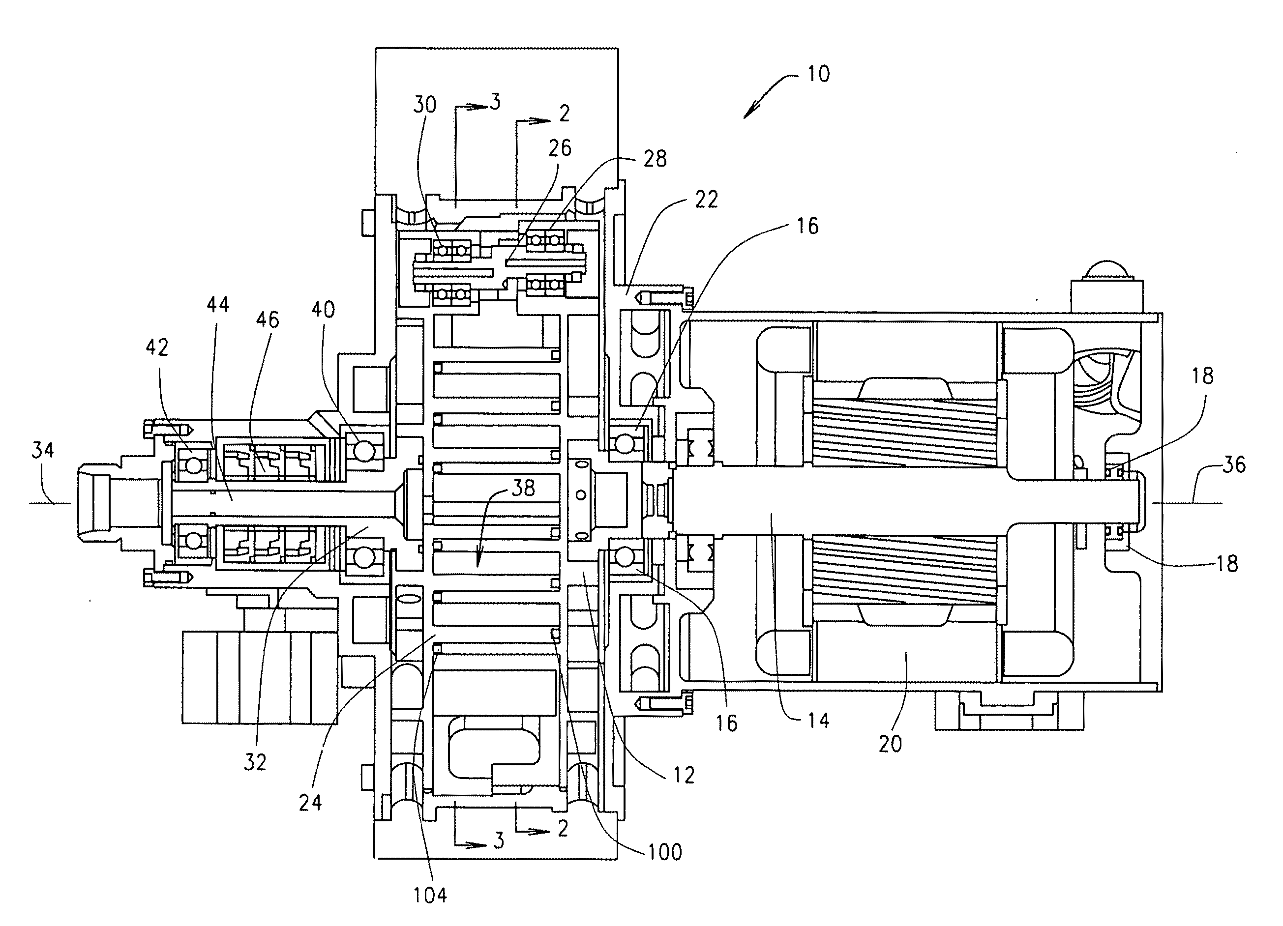
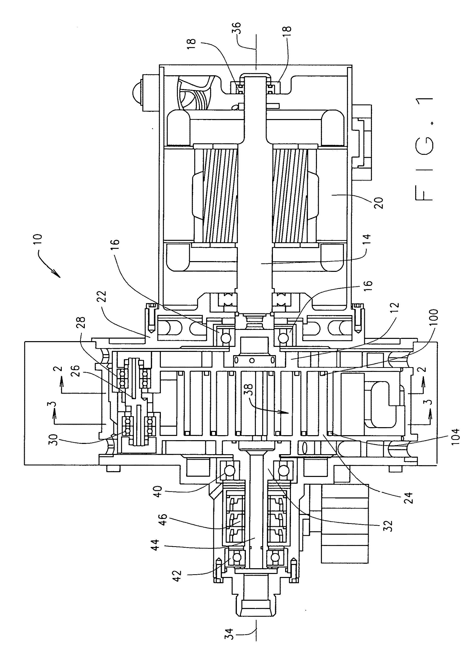
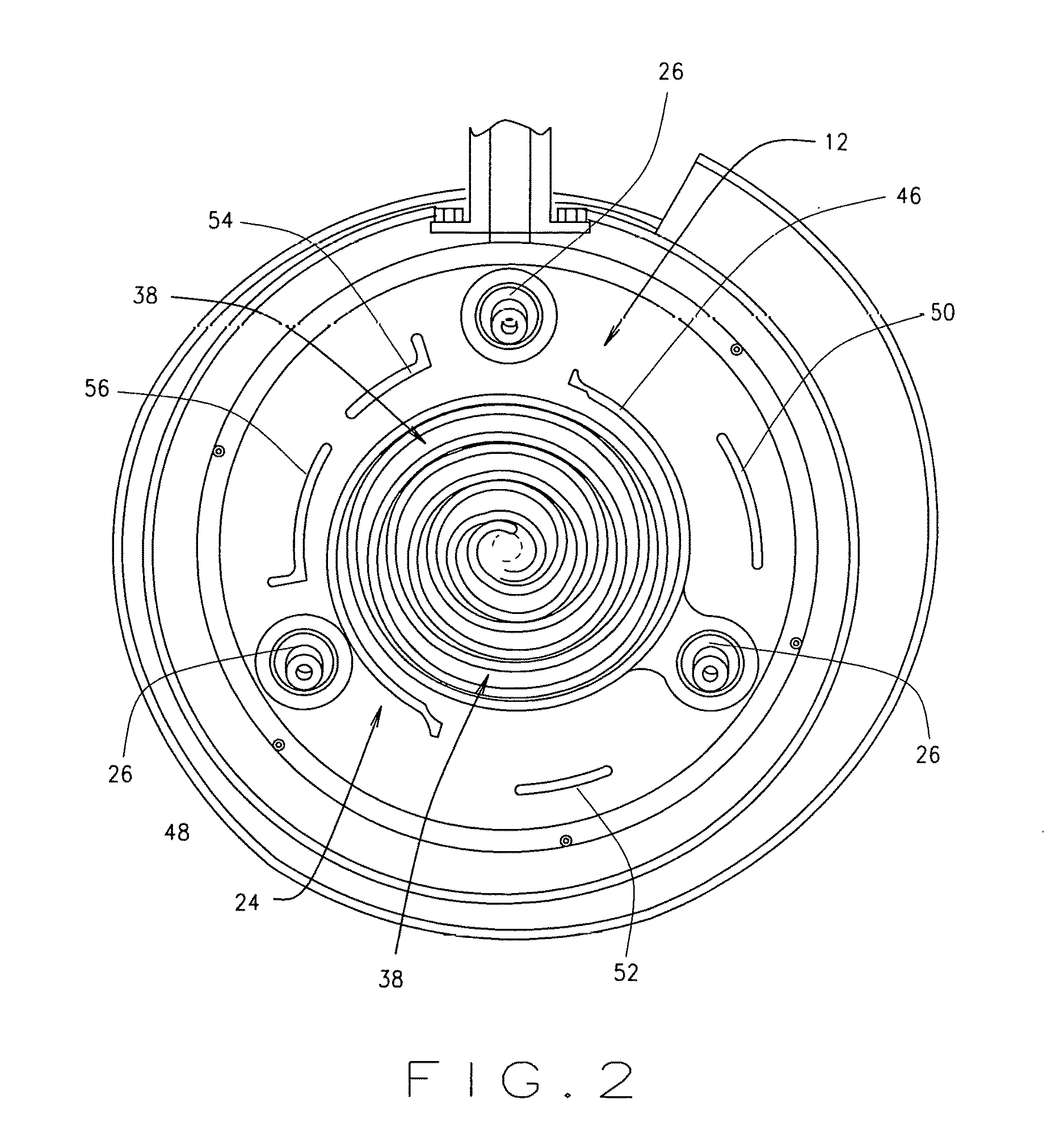
[0038]Referring now to the drawings, wherein like numbers refer to like items, number 10 identifies a preferred embodiment of a co-rotating scroll device constructed according to the present disclosure. In FIG. 1, the co-rotating scroll device 10 is shown to comprise a drive scroll 12 which is driven by a center shaft 14. The center shaft 14 is supported by a front bearing 16 and a rear bearing 18. An electric motor 20 is used to drive the center shaft 14. The bearings 16 and 18 and the electric motor 20 are mounted in a housing 22. A second scroll or driven scroll 24 is driven by the drive scroll 12 through the use of idler shafts 26, of which only one idler shaft 26 is shown in this view. By way of example there may be three idler shafts 26 that are spaced 120° apart. The idler shaft 26 is supported by a first bearing 28 in the drive scroll 12 and a second bearing 30 in the driven scroll 24. A shaft 32 is connected to the driven scroll 24. A center line 34 of the shaft 32 is offse...


PUM


Abstract

A co-rotating scroll is disclosed having a motor having a shaft, a drive scroll connected to the shaft for moving the drive scroll, a driven scroll connected to the drive scroll to be moved by the drive scroll, and an idler shaft for aligning the drive scroll and the driven scroll and for allowing the driven scroll to be moved by the drive scroll.

Description

CROSS REFERENCE TO RELATED APPLICATION[0001]This provisional patent application claims priority to the provisional patent application having Ser. No. 62 / 179,437, filed on May 7, 2015; said earlier provisional patent application claims priority to the non-provisional patent application having Ser. No. 14 / 544,874, filed on Feb. 27, 2015; which claims priority as a continuation-in-part patent application to the patent application having Ser. No. 13 / 987,486, filed on Jul. 30, 2013, which claims priority to the non provisional patent application having Ser. No. 13 / 066,261, filed on Apr. 11, 2011, now U.S. Pat. No. 8,523,544, which claims priority to the provisional patent application having Ser. No. 61 / 342,690, filed on Apr. 16, 2010, which claims priority to the non-provisional patent application having Ser. No. 12 / 930,140, filed on Dec. 29, 2010, now U.S. Pat. No. 8,668,479, which claims priority to the provisional patent application having Ser. No. 61 / 336,035, filed on Jan. 16, 2010, ...

Claims


Application Information

Patent Timeline
IPC IPC(8): F04C29/00F04C18/02F04C15/00F04C2/02
CPCF04C29/005F04C2/02F04C18/023F04C2240/60F04C15/0061F04C29/0085F04C2240/50F04C15/008F01C1/0261F01C17/063F01C21/008F04C2240/80F04C23/008
Inventor SHAFFER, ROBERT W.SHAFFER, BRYCE R.VIGIL, RUSSELL
Owner AIR SQUARED
Why Eureka
Try Eureka