Circular polarizer for organic el display device, and organic el display device

Active Publication Date: 2017-02-23
NITTO DENKO CORP
View PDF5 Cites 11 Cited by
  • Summary
  • Abstract
  • Description
  • Claims
  • Application Information

AI Technical Summary

Benefits of technology

[0011]According to the present invention, a polarizer and two specific retardation layers are laminated at specific axial angles, and hence the circularly polar

Problems solved by technology

The organic EL panel is liable to cause problems, such as ambient light reflection and background reflection, because the panel includes a metal layer having high reflectivity.
However, a conventional circularly polarizing plate involves the fol

Method used


Image

  • Circular polarizer for organic el display device, and organic el display device
  • Circular polarizer for organic el display device, and organic el display device
  • Circular polarizer for organic el display device, and organic el display device

Examples


Example

Example 1

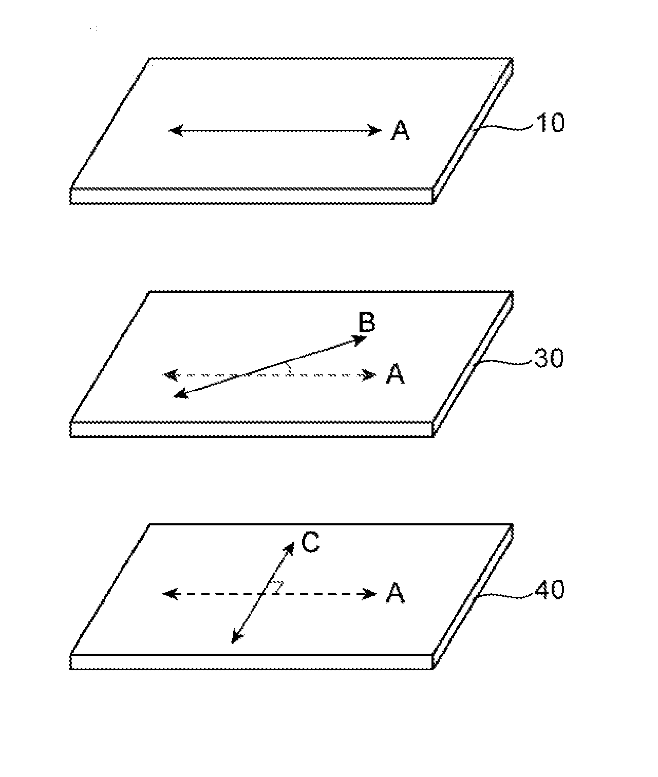
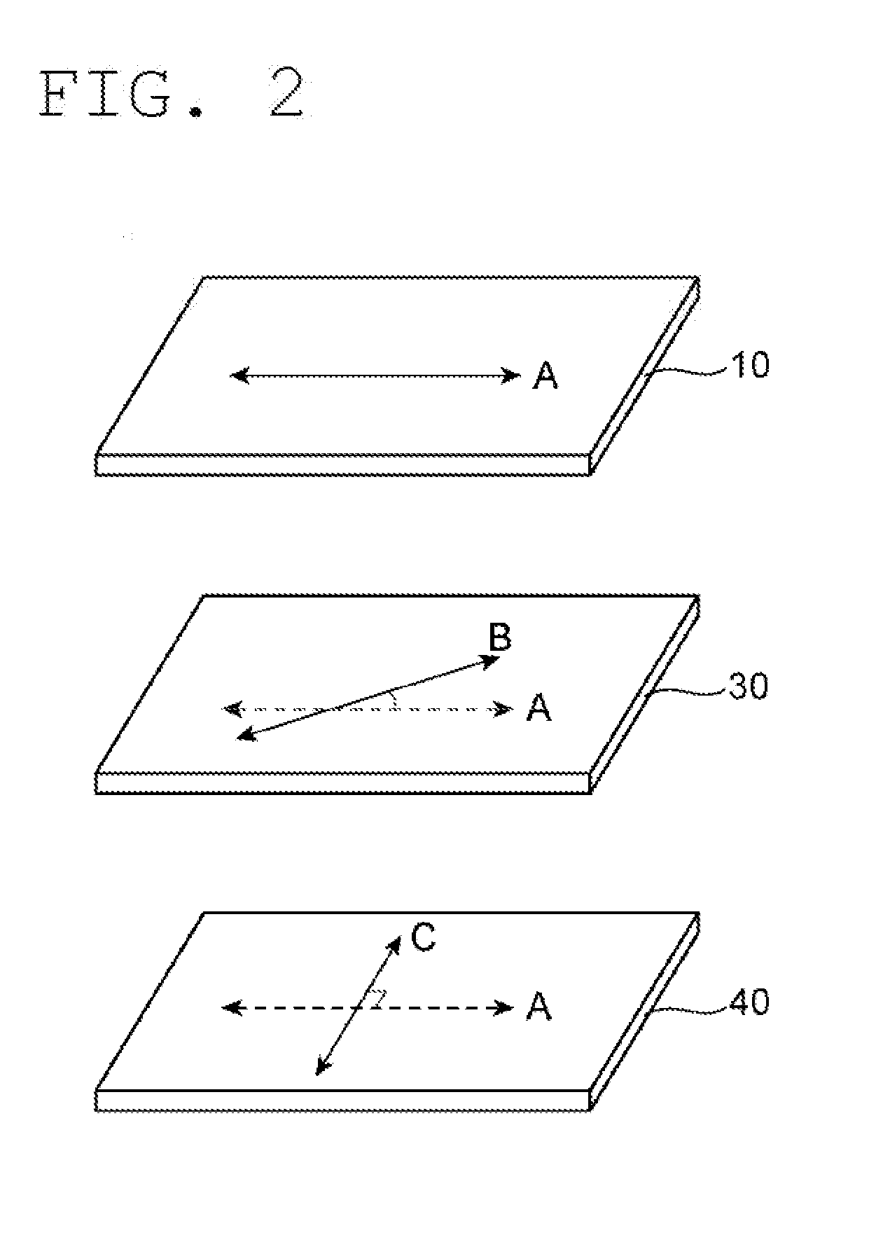
[0100]A roll-shaped unstretched film made of a norbornene-based resin having a photoelastic coefficient of 11×10−12 m2 / N, a Tg of 125° C., and a thickness of 70 μm was obliquely stretched under an atmosphere at 133° C. The oblique stretching was continuously performed with a tenter-type stretching machine by making its left and right feeding speeds different from each other. As a result, a roll-shaped retardation film having a thickness of 45 μm was obtained. The in-plane retardation Re(550) of the retardation film was 270 nm, and the direction of its slow axis was a 22.5° direction with regard to the longitudinal direction of the film. The retardation film was used as a first retardation layer.

[0101]A roll-shaped unstretched film made of a norbornene-based resin having a photoelastic coefficient of 11×10−12 m2 / N, a Tg of 125° C., and a thickness of 50 μm was subjected to lateral uniaxial stretching at 1.526 times under an atmosphere at 128° C. to provide a roll-shaped reta...

Example

Example 2

[0106]An optical alignment film was formed by application on the surface of the second retardation layer obtained in Example 1, and the resultant was subjected to an optical alignment treatment in a 22.5° direction with regard to its longitudinal direction. Meanwhile, a liquid crystal application liquid was prepared by dissolving 10 parts by weight of a polymerizable liquid crystal monomer showing a nematic liquid crystal phase (manufactured by BASF: trade name: “Paliocolor LC242”) and 3 parts by weight of a photopolymerization initiator (manufactured by BASF: trade name: “IRGACURE 907”) for the polymerizable liquid crystal monomer in 40 parts by weight of toluene. The application liquid was applied to the surface of the second retardation layer subjected to the optical alignment treatment with a bar coater, and then a liquid crystal was aligned by heating and drying the liquid at 80° C. for 4 minutes. The liquid crystal layer was cured by being irradiated with UV light, an...

Example

Comparative Example 1

[0108]A roll-shaped unstretched film made of a norbornene-based resin having a photoelastic coefficient of 11×10−12 m2 / N, a Tg of 125° C., and a thickness of 50 μm was subjected to longitudinal uniaxial stretching at 1.526 times under an atmosphere at 128° C. with rolls having different peripheral speeds to provide a roll-shaped retardation film having a thickness of 40 μm. The in-plane retardation Re(550) of the retardation film was 140 nm, and the direction of its slow axis was the longitudinal direction of the film. The retardation film was used as a second retardation layer.

[0109]A circularly polarizing plate and an organic EL display apparatus were obtained in the same manner as in Example 1 except that the second retardation layer obtained in the foregoing was used. In the resultant roll-shaped circularly polarizing plate, the absorption axis of the polarizer was in its longitudinal direction, an angle formed between the absorption axis of the polarizer an...


PUM

PropertyMeasurementUnit
Angleaaaaaaaaaa
Angleaaaaaaaaaa
Refractive indexaaaaaaaaaa

Abstract

There is provided a circularly polarizing plate for an organic EL display apparatus that is excellent in productivity, is prevented from warping, and can achieve an excellent tint. An elongated circularly polarizing plate for an organic EL display apparatus according to an embodiment of the present invention includes in the following order: an elongated polarizer having an absorption axis in a longitudinal direction thereof; an elongated first retardation layer functioning as a λ/2 plate; and an elongated second retardation layer functioning as a λ/4 plate. An angle formed between the absorption axis of the elongated polarizer and a slow axis of the elongated first retardation layer is front 15° to 30°; and the absorption axis of the elongated polarizer and a slow axis of the elongated second retardation layer are substantially perpendicular to each other.

Description

TECHNICAL FIELD[0001]The present invention relates to a circularly polarizing plate for an organic EL display apparatus and an organic EL display apparatus.BACKGROUND ART[0002]In recent years, a display mounted with an organic EL panel has been proposed in association with widespread use of a thin display. The organic EL panel is liable to cause problems, such as ambient light reflection and background reflection, because the panel includes a metal layer having high reflectivity. In view of the foregoing, it has been known that those problems are prevented by arranging a circularly polarizing plate on a viewer side. A circularly polarizing plate obtained by laminating a polarizer, a λ / 2 plate, and a λ / 4 plate has been known as a general circularly polarizing plate (e.g., Patent Literatures 1 and 2). However, a conventional circularly polarizing plate involves the following problems. It is difficult to produce the plate by the so-called roll-to-roll process and hence the plate is poo...

Claims


Application Information

Patent Timeline
IPC IPC(8): G02B5/30H01L51/52
CPCG02B5/3083H05B33/12H01L51/5281B32B27/00B32B7/06B32B7/12B32B27/08B32B27/286B32B27/302B32B27/306B32B27/308B32B27/325B32B27/36B32B27/365G02B5/305B32B2250/05B32B2307/418B32B2307/42B32B2307/514B32B2457/206B32B7/03H10K50/86G02B5/30H01L33/02H10K50/00
Inventor TAKEDA, KENTAROUYAGINUMA, HIRONORIUWADA, KAZUKIKOJIMA, TADASHIMURAKAMI, NAO
Owner NITTO DENKO CORP
Why Eureka
Try Eureka