Driving circuit for a vibration type actuator, vibration device, image blur correction apparatus, replacement lens, image pickup apparatus, and automatic stage

Active Publication Date: 2017-02-23
CANON KK
View PDF4 Cites 9 Cited by
  • Summary
  • Abstract
  • Description
  • Claims
  • Application Information

AI Technical Summary

Benefits of technology

[0010]However, the above-described technology is not focused on a phenomenon that a voltage variation in a driving circuit is caused by a change in an impedance in an unwa

Problems solved by technology

However, the above-described technology is not focused on a phenomenon that a voltage variation in a driving circuit is caused by a change in an impedance in an unwante

Method used


Image

  • Driving circuit for a vibration type actuator, vibration device, image blur correction apparatus, replacement lens, image pickup apparatus, and automatic stage
  • Driving circuit for a vibration type actuator, vibration device, image blur correction apparatus, replacement lens, image pickup apparatus, and automatic stage
  • Driving circuit for a vibration type actuator, vibration device, image blur correction apparatus, replacement lens, image pickup apparatus, and automatic stage

Examples


first exemplary embodiment

Descriptions of a Principle of a Chip Vibrator

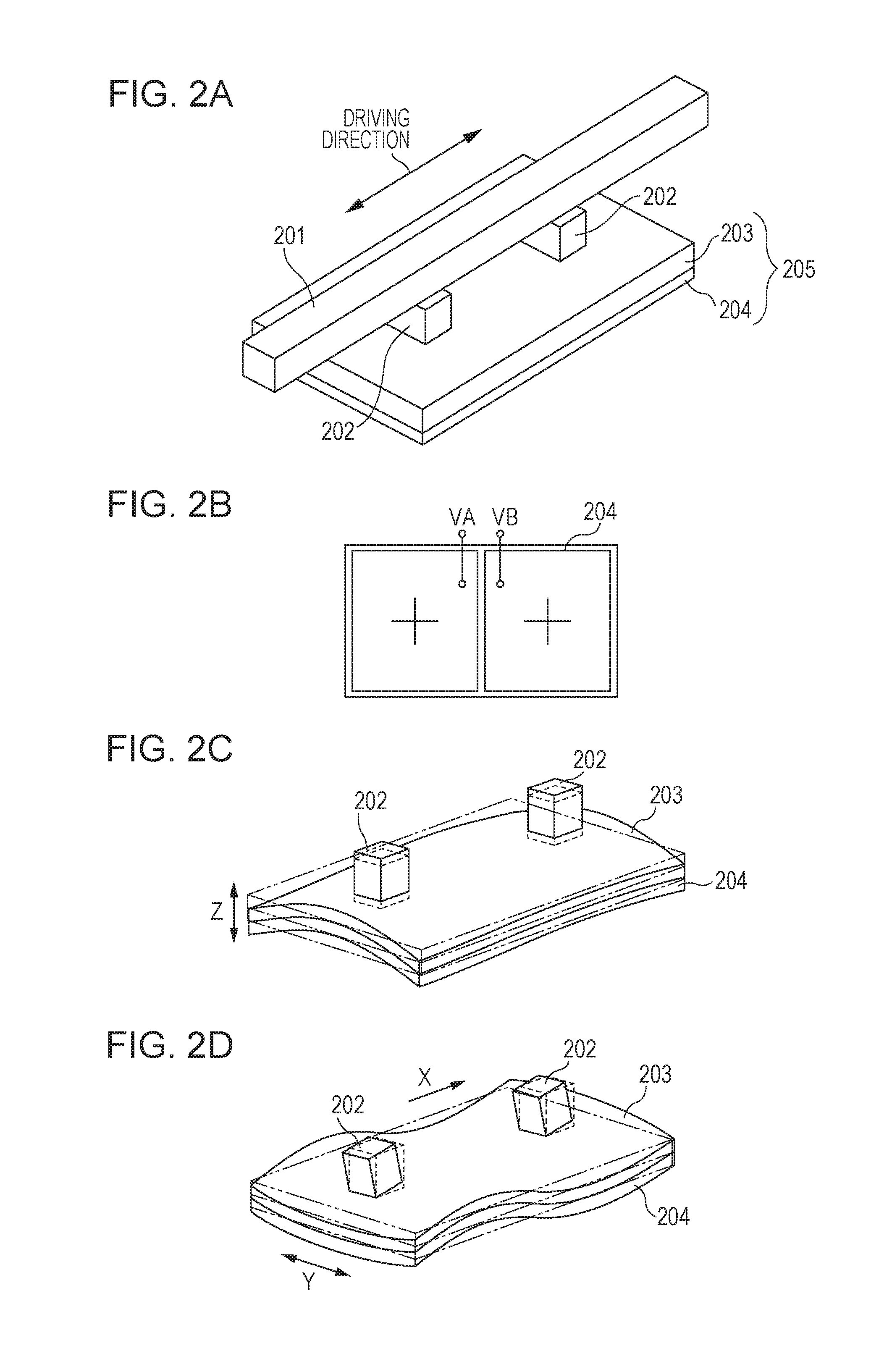
[0034]FIGS. 2A to 2D are explanatory diagrams for describing a driving principle of the vibration type actuator of a linear driving type. The vibration type actuator illustrated in FIG. 2A is constituted by, or includes, a vibrator 205 in which a piezoelectric element 204 is bonded to an elastic member 203 and the driven member 201 driven by the vibrator 205. While AC voltages are applied to the piezoelectric element 204, two vibration modes illustrated in FIGS. 2C and 2D are generated, and the driven member 201 in pressure contact with protruding portions 202 in an arrow direction.

[0035]FIG. 2B illustrates an electrode pattern of the piezoelectric element 204. For example, electrode areas divided into half in a longitudinal direction are formed in the piezoelectric element 204 of the vibrator 205. Polarization directions of the respective electrode areas are the same direction (+). Among the two electrode areas of the piezoelectric elem...

second exemplary embodiment

[0077]Next, a second exemplary embodiment will be described with reference to FIG. 7. The present exemplary embodiment is different from the first exemplary embodiment in that boosting is performed by using a transformer and a coil.

[0078]FIG. 7 illustrates a vibration device including a driving circuit for a vibration type actuator and the above-described vibration type actuator according to the second exemplary embodiment. According to the configuration of the driving circuit, a first terminal of the piezoelectric element 101 and a first terminal on a secondary side coil of a transformer 105 are electrically connected to each other, and a second terminal of the piezoelectric element 101 and a second terminal of the secondary side coil are electrically connected to each other. That is, the AC voltage Vo applied between the two terminals of the piezoelectric element 101 is equal to a voltage Vo applied between the two terminals of the secondary side coil of the transformer 105. In ad...

third exemplary embodiment

Circuit with a Resistance Arranged in Parallel

[0095]Next, a third exemplary embodiment will be described. FIGS. 13A to 13C illustrate a vibration device including a driving circuit for the vibration type actuator and the vibration type actuator according to the third exemplary embodiment. According to the present exemplary embodiment, attenuation of the current flowing through the piezoelectric element at the unwanted vibration frequency fu can be realized, and the effect of further suppressing the unwanted vibration can be attained.

[0096]FIG. 13A illustrates a configuration in which an impedance (Z) element 1301 is connected in parallel to a set of the inductor 102 and the capacitor 103. As the impedance element, an element having a resistance component to an AC signal such as a resistance, a condenser, or a coil is used. FIG. 13B illustrates a configuration in which a resistance 1302 is connected in parallel to a set of the inductor 102 and the capacitor 103. For example, fs and f...


PUM


Abstract

A driving circuit for a vibration type actuator includes an inductor and a capacitor which are connected in series to an electric-mechanical energy conversion element, in which, in a case where a series resonance frequency based on the inductor and the capacitor is set as fs, and a resonance frequency in a vibration mode other than vibration used for driving of the vibrator is set as fu, 0.73·fu<fs<1.2·fu is satisfied.

Description

BACKGROUND OF THE INVENTION[0001]Field of the Invention[0002]One disclosed aspect of the embodiments relates, for example, to a driving circuit for a vibration type actuator, a vibration device, an image blur correction apparatus, a replacement lens, an image pickup apparatus, and an automatic stage.[0003]Description of the Related Art[0004]A vibration type motor is an example of a vibration type actuator and includes an elastic member, a vibrator including an electric-mechanical energy conversion element such as a piezoelectric element coupled to the elastic member, and a driven member in pressure contact with the vibrator. The vibration type motor is a non-electromagnetic driving system motor arranged to apply an alternating-current (AC) voltage to the electric-mechanical energy conversion element to generate a high-frequency vibration in the element and take out the vibration energy as a continuous machine motion.[0005]A control apparatus for the vibration type actuator includes ...

Claims


Application Information

Patent Timeline
IPC IPC(8): H02N2/06G02B21/26H04N5/232G02B27/64
CPCH02N2/06H04N5/23287G02B21/26G02B27/646H02N2/04H02N2/08G03B13/36G03B13/34H02N2/0015H02N2/0075H02N2/026H02N2/065G02B7/08H04N23/687H02N2/008H02M7/523
Inventor SUMIOKA, JUN
Owner CANON KK
Why Eureka
Try Eureka