
Surface modeling

a surface modeling and surface technology, applied in the field of surface modeling, can solve the problems of generating an accurate representation of the outer surface of an object using existing modeling tools, changing the shape of the outside of the aircraft's skin, and using modeling tools

Active Publication Date: 2017-03-02
THE BOEING CO
View PDF4 Cites 4 Cited by
  • Summary
  • Abstract
  • Description
  • Claims
  • Application Information

AI Technical Summary

Benefits of technology

The patent text describes a method and system for creating a model of a surface using a reference design and a second set of composite materials. The reference design includes first geometrical information associated with a first set of composite materials to form a reference surface. The second set of composite materials is associated with a second design, and the first and second geometrical information are compared to determine an offset surface relative to the reference surface. The model of the surface of the second design is then generated based on the reference surface and the offset surface. The technical effect of this technology is to allow for precise modeling of surfaces using composite materials and reference designs.

Problems solved by technology

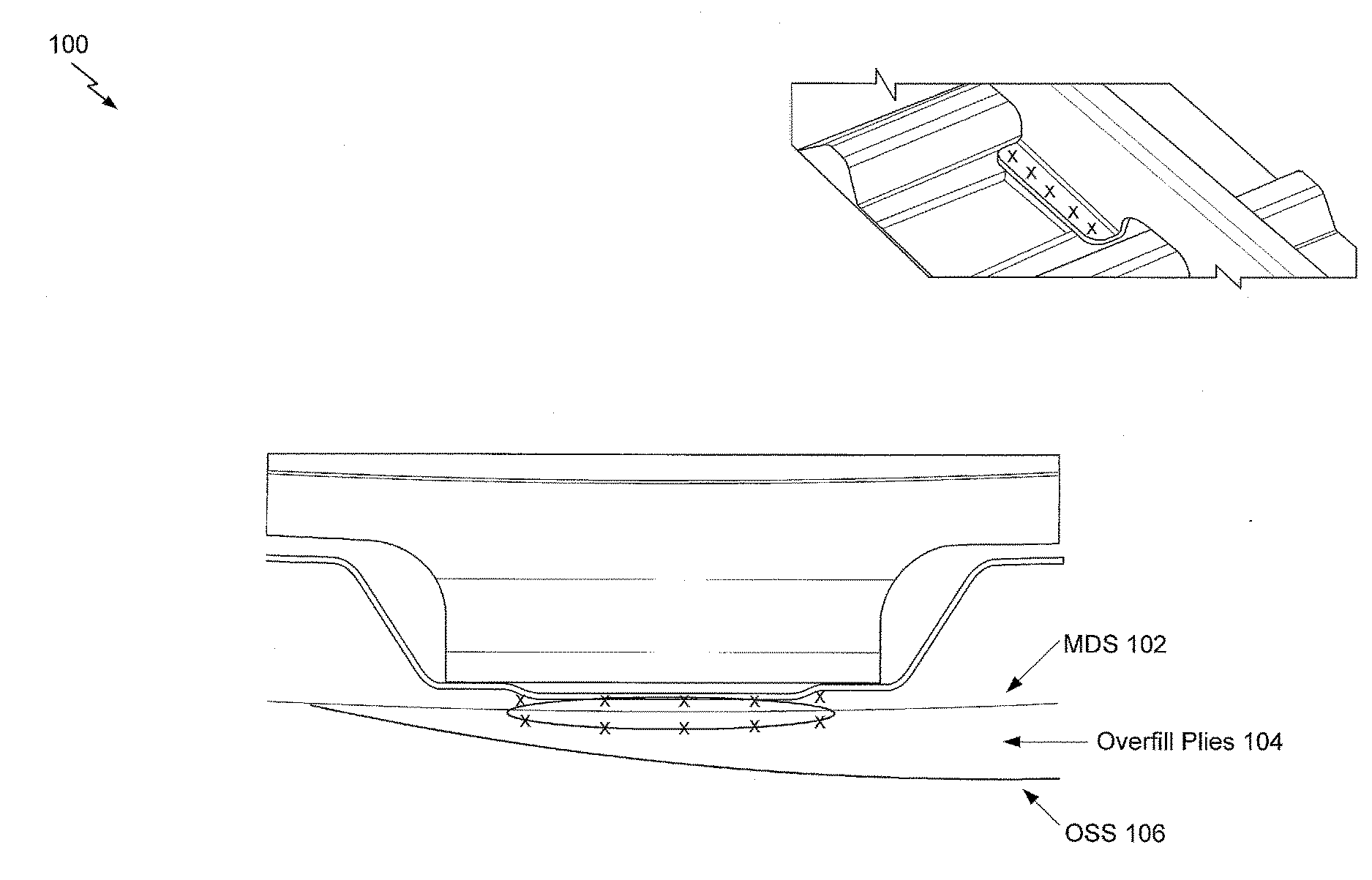
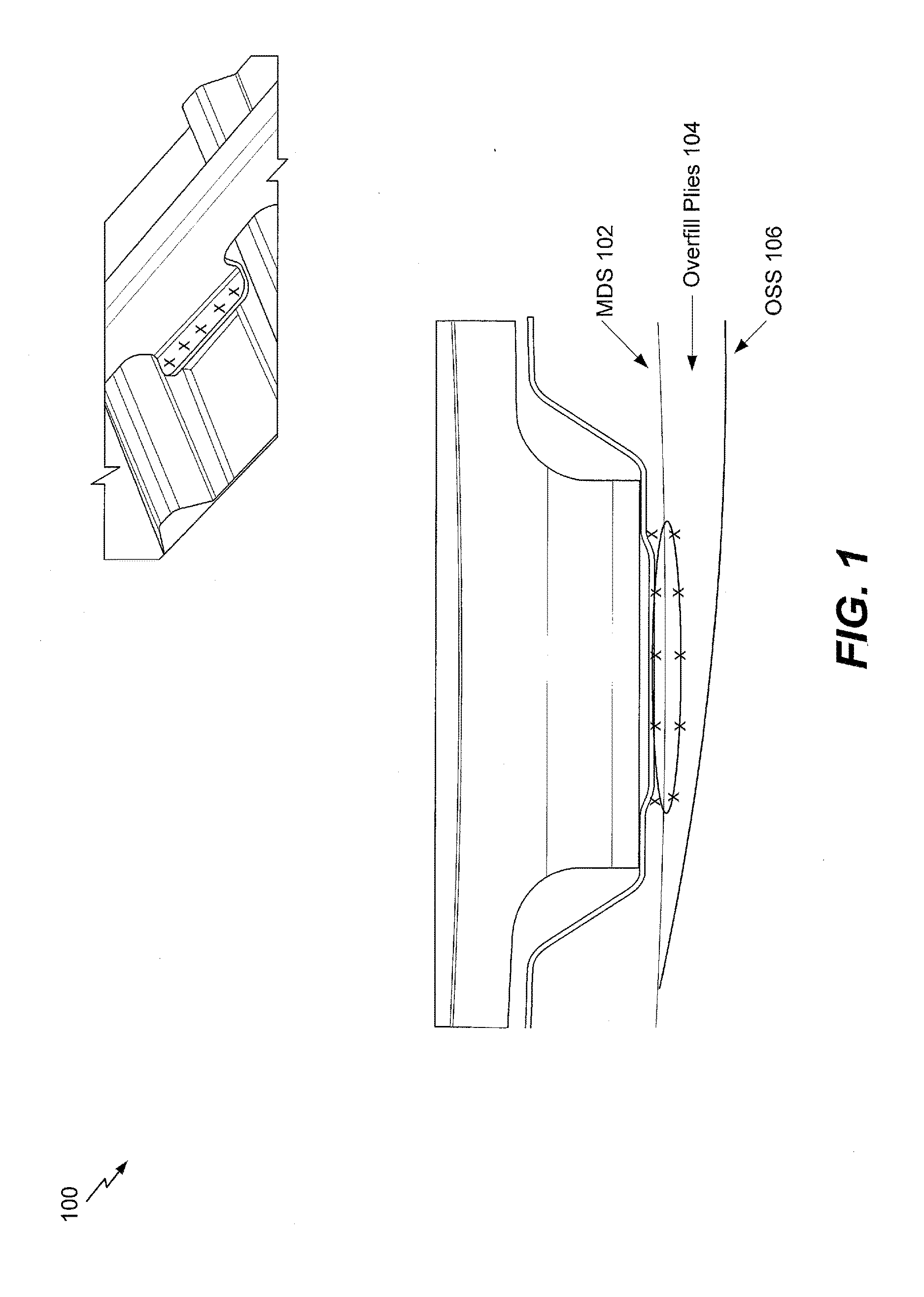
Since the outer surface can vary a bit, generating an accurate representation of an outer surface of an object may be difficult using existing modeling tools.
The addition of such composite plies results in a change of shape of an outside of the aircraft's skin.
Utilizing a modeling tool to calculate the offset from a fixed reference surface (referred to herein as a master datum surface (MDS)) to model the OSS may be insufficient, as such modeling only builds in one direction.
Attempting to model in one direction at a time, even if successful, may yield an inaccurate surface.
However, such sampling may be limited in order to reduce memory utilization.

Method used


Image

  • Surface modeling
  • Surface modeling
  • Surface modeling

Examples


Embodiment Construction

[0022]In some cases, fuselages for different aircraft designs may use the same internal interface for frames and stringers (referred to herein as an “inner skin assembly” or ISA), in order to have as many commonalities as possible to reduce re-engineering. In the case of a stretched fuselage skin, additional composite plies may be utilized to meet the aircraft's structural requirements. The addition of such composite plies results in a change of shape of an outside of the aircraft's skin. In order to fasten frames and other parts to the aircraft's skin, engineers rely on a precise shape of the final aircraft skin (referred to herein as an “outer skin surface” or OSS). Shapes of ply ramps are particularly important (e.g., for accurate identification of fastener locations). The model of the present disclosure may be used for the purposes of drilling holes for fasteners. It may be desirable for the fasteners to be attached to a fuselage (or other aircraft component) substantially perpe...


PUM


Abstract

A method includes receiving a reference design at a computing device. The reference design includes first geometrical information associated with a first set of composite materials to form a reference surface. The method includes receiving second geometrical information at the computing device. The second geometrical information is associated with a second set of composite materials associated with a second design. The method includes determining, based on a comparison of the first geometrical information and the second geometrical information, an offset surface relative to the reference surface. The method further includes generating a model of a surface of the second design based on the reference surface and the offset surface.

Description

FIELD[0001]The present disclosure generally relates to surface modeling.BACKGROUND[0002]Composite parts are generally formed by laying up layers on a die. The die constrains a shape of one side of the composite part; however, a shape of the other side (e.g., the outer surface) of the composite surface may vary a bit due to how the layers stack. Since the outer surface can vary a bit, generating an accurate representation of an outer surface of an object may be difficult using existing modeling tools.SUMMARY[0003]In an embodiment, a method includes receiving a reference design at a computing device. The reference design includes first geometrical information associated with a first set of composite materials to form a reference surface. The method includes receiving second geometrical information at the computing device. The second geometrical information is associated with a second set of composite materials associated with a second design. The method includes determining, based on ...

Claims


Application Information

Patent Timeline
IPC IPC(8): B64F5/00
CPCB64F5/00G06F30/15B64C2001/0072B29C51/14F01D5/282F05D2300/603G06F30/00G06F30/17G06F30/20G06F2113/26G06F2119/18G06F2113/28
Inventor BLANARIK, TREVOR C.STENGEL, JOSHUA M.DIXON, STEVEN M.
Owner THE BOEING CO
Learn More