
Variable pitch fan pitch range limiter

a variable pitch fan and limiter technology, which is applied in the direction of rotors, machines/engines, liquid fuel engines, etc., can solve problems such as damag

Active Publication Date: 2017-03-02
GENERAL ELECTRIC CO
View PDF3 Cites 4 Cited by
  • Summary
  • Abstract
  • Description
  • Claims
  • Application Information

AI Technical Summary

Benefits of technology

The present invention provides certain technical effects that are described in detail in the patent text. These technical effects are achieved through a set of features and aspects that are outlined in the patent. The accompanying drawings, which are also incorporated in the patent, show examples of how these features and aspects work. Overall, the invention provides improved performance and efficiency in a specific field.

Problems solved by technology

If such takes place during forward flight, damage may occur.

Method used


Image

  • Variable pitch fan pitch range limiter
  • Variable pitch fan pitch range limiter
  • Variable pitch fan pitch range limiter

Examples


Embodiment Construction

[0025]Reference will now be made in detail to present embodiments of the invention, one or more examples of which are illustrated in the accompanying drawings. The detailed description uses numerical and letter designations to refer to features in the drawings. Like or similar designations in the drawings and description have been used to refer to like or similar parts of the invention. As used herein, the terms “first”, “second”, and “third” may be used interchangeably to distinguish one component from another and are not intended to signify location or importance of the individual components. The terms “upstream” and “downstream” refer to the relative direction with respect to fluid flow in a fluid pathway. For example, “upstream” refers to the direction from which the fluid flows, and “downstream” refers to the direction to which the fluid flows. In addition, it should be appreciated that the term “fluid” as used herein includes any material or medium that flows, including, but n...


PUM


Abstract

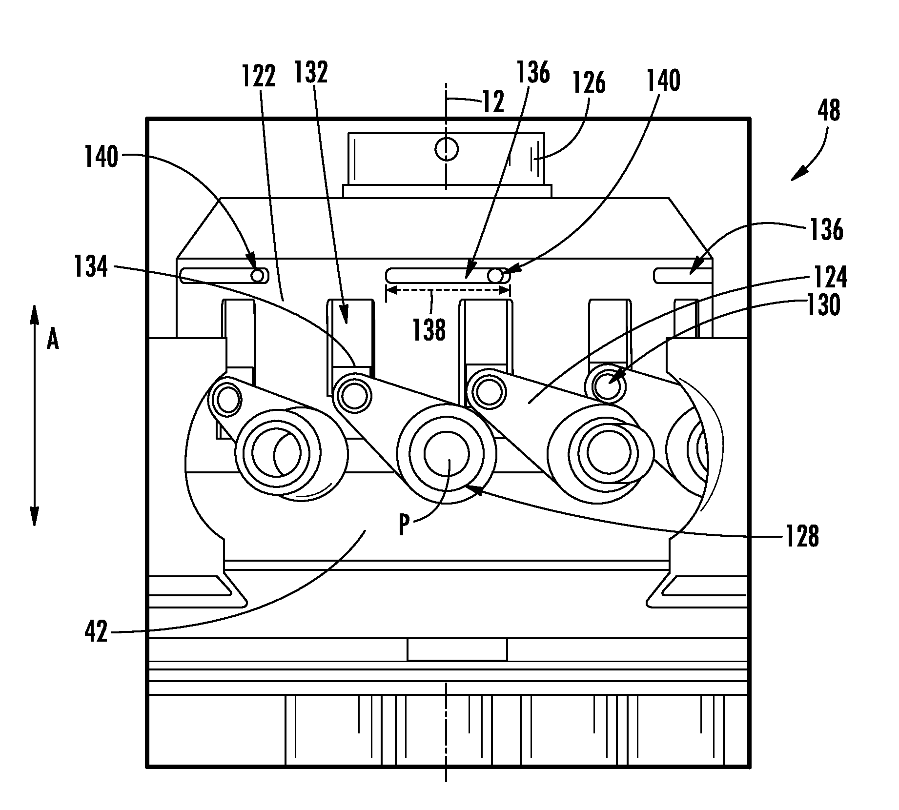
A variable pitch fan for gas turbine engine is provided. The variable pitch fan includes a plurality of fan blades rotatably coupled to a disk and an actuation assembly for changing a pitch of each of the plurality of fan blades. The actuation assembly generally includes an actuation member operably connected to at least one of the plurality of fan blades and a pin. The pin is movable between a first position in which the pin is positioned at least partially in a channel defined in the actuation member, and a second position. The pin blocks movement of the actuation member relative to the pin past a range defined by the channel when in the first position. The actuation assembly further includes a retraction system for selectively engaging the pin in moving the pin from the first position to the second position.

Description

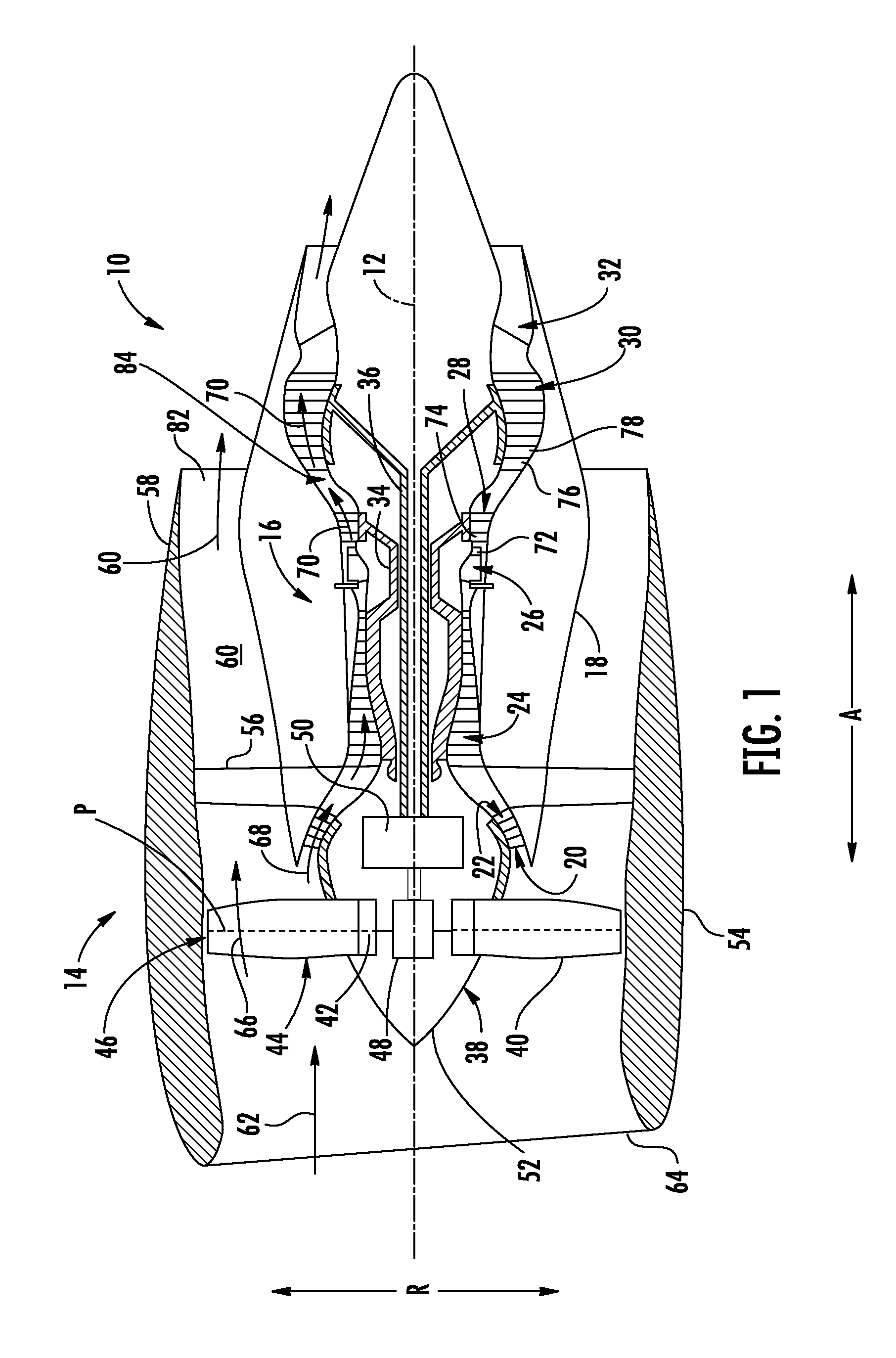
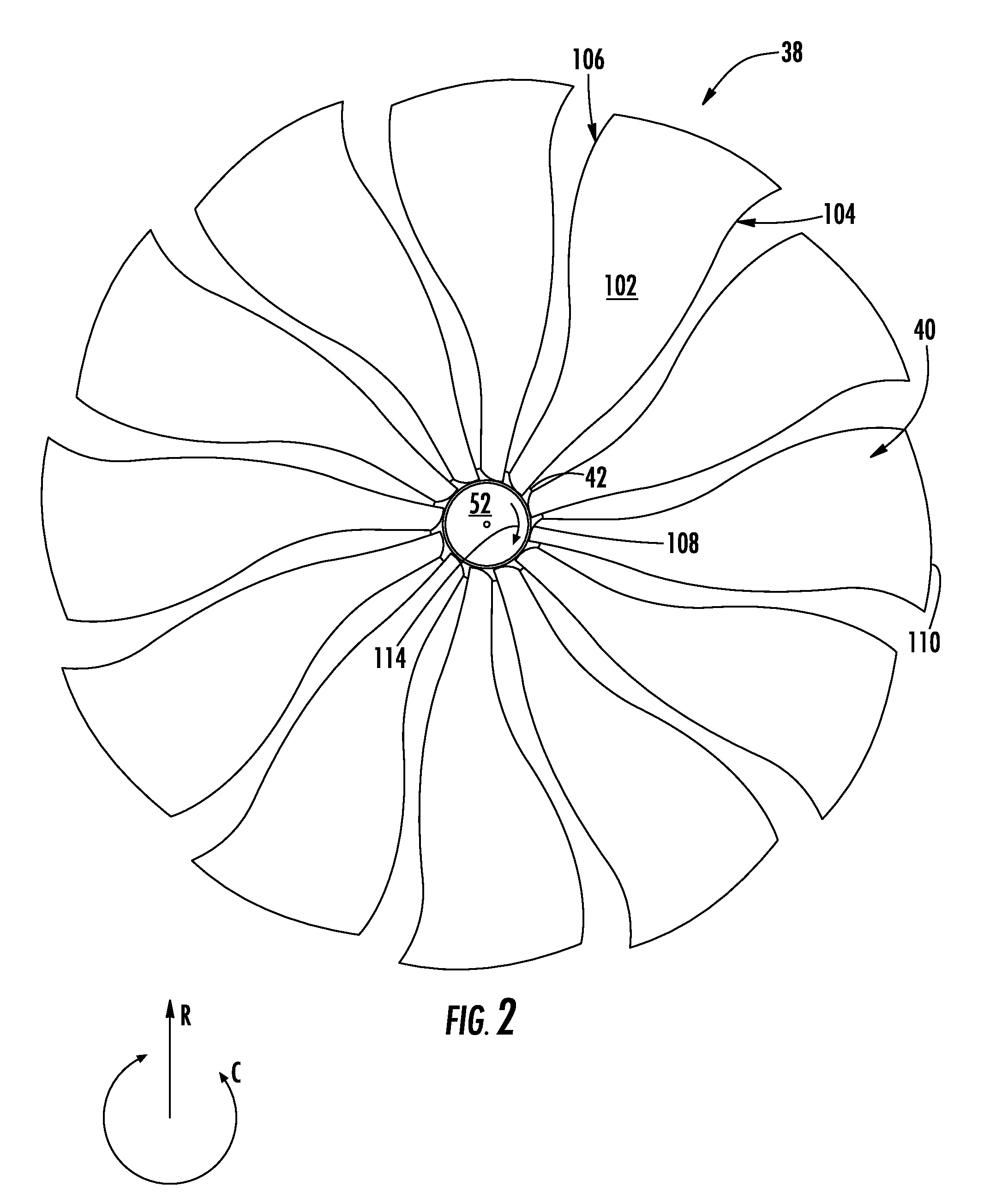
FIELD OF THE INVENTION[0001]The present subject matter relates generally to a variable pitch fan for a gas turbine engine, or more particularly to a variable pitch fan for a gas turbine engine having a pitch range limiter.BACKGROUND OF THE INVENTION[0002]A gas turbine engine generally includes a fan and a core arranged in flow communication with one another. Additionally, the core of the gas turbine engine generally includes, in serial flow order, a compressor section, a combustion section, a turbine section, and an exhaust section. In operation, an airflow is provided from the fan to an inlet of the compressor section where one or more axial compressors progressively compress the air until it reaches the combustion section. Fuel is mixed with the compressed air and burned within the combustion section to provide combustion gases. The combustion gases are routed from the combustion section to the turbine section. The flow of combustion gases through the turbine section drives the co...

Claims


Application Information

Patent Timeline
Patent Type & Authority Applications(United States)
IPC IPC(8): F01D7/00
CPCF01D7/00F05D2220/36F05D2260/76F05D2240/30F05D2260/74F02C9/20B64C11/38B64C11/44F02K1/66F04D27/0292F04D29/323F05D2260/72F05D2270/46F05D2270/56F05D2270/62F05D2270/64F02C9/58Y02T50/60B64C11/00
Inventor NIERGARTH, DANIEL ALANMILLER, BRANDON WAYNE
Owner GENERAL ELECTRIC CO
Learn More