
Multi-mode variable cam timing phaser

a variable cam timing and phaser technology, applied in machine/engines, valve details, valve arrangements, etc., can solve the problem that not all engines provide enough camshaft torque energy throughout the entire engine operation

Active Publication Date: 2017-03-02
BORGWARNER INC
View PDF0 Cites 16 Cited by
  • Summary
  • Abstract
  • Description
  • Claims
  • Application Information

AI Technical Summary

Benefits of technology

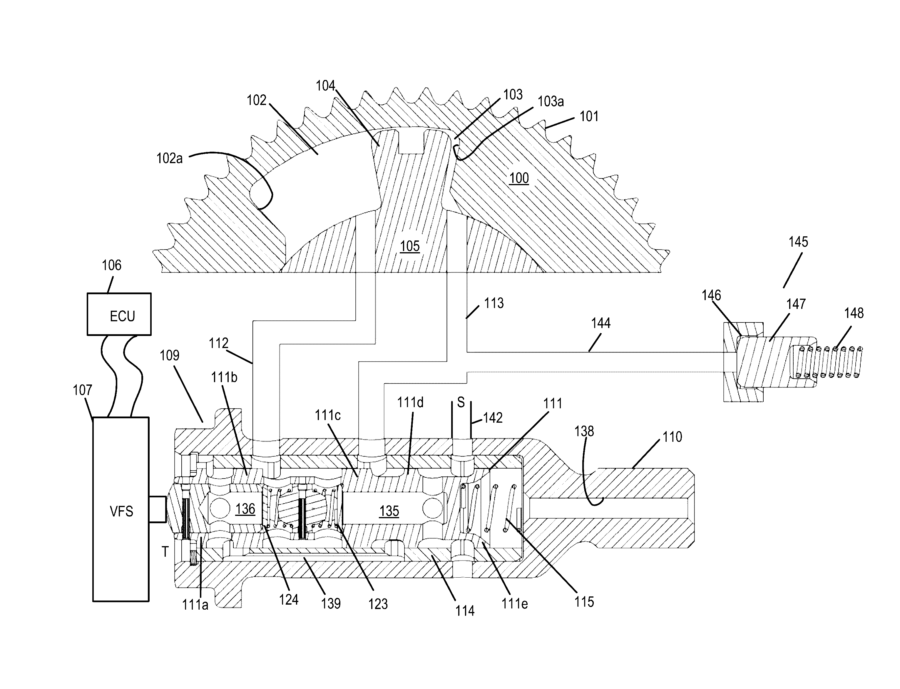
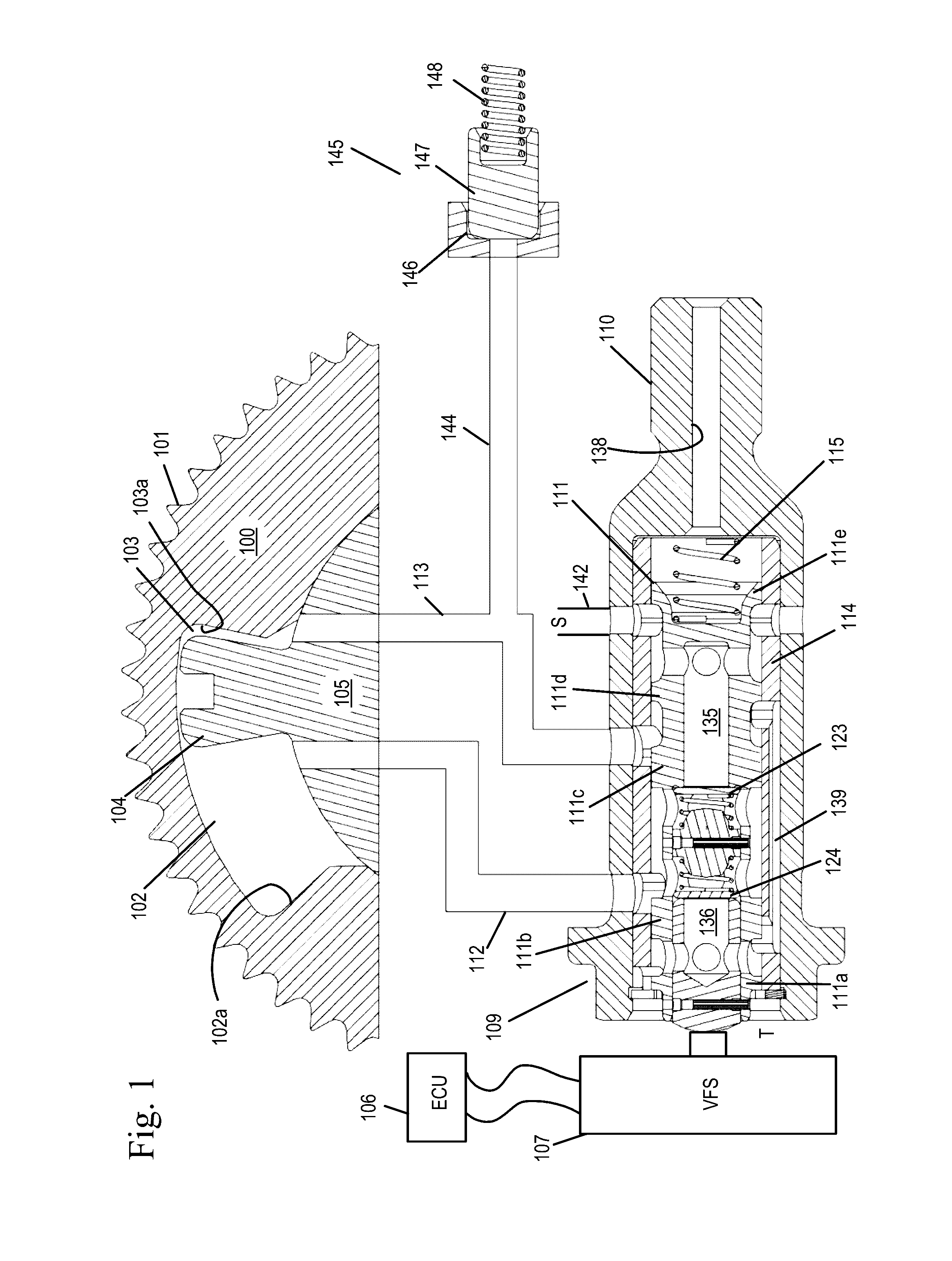
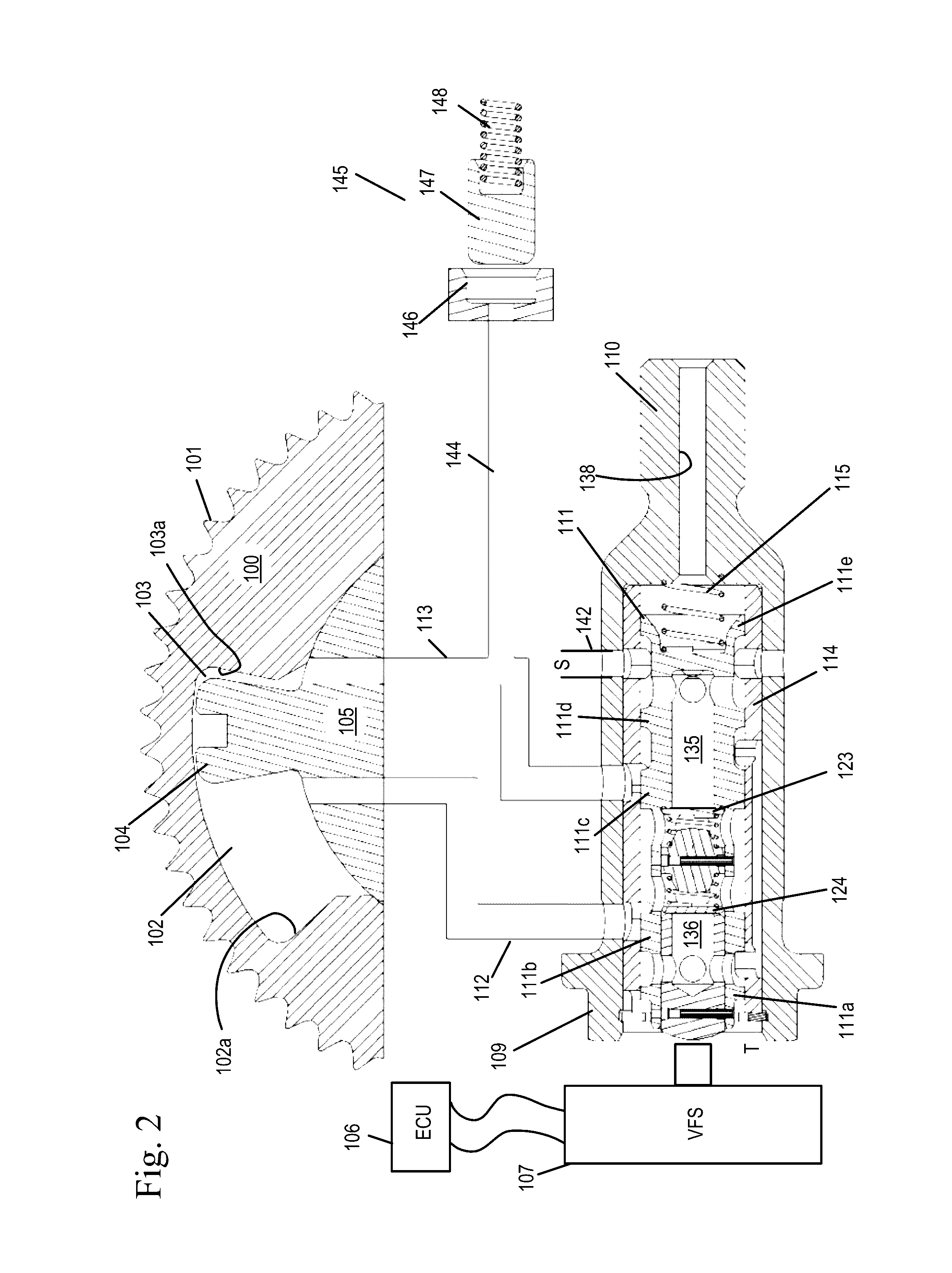
This patent describes a device that controls the timing of camshafts in an internal combustion engine. The device uses the energy from the camshaft to transfer fluid between two chambers and can also receive additional fluid during recirculation. A lock pin is controlled by the position of a spool to achieve the desired timing. The technical effect of this invention is to improve engine performance by optimizing camshaft timing.

Problems solved by technology

However, not all engines provide enough camshaft torque energy throughout the entire engine operating range to effectively phase the variable camshaft timing device.

Method used


Image

  • Multi-mode variable cam timing phaser
  • Multi-mode variable cam timing phaser
  • Multi-mode variable cam timing phaser

Examples


Embodiment Construction

[0026]In an embodiment of the present invention, the control valve may direct fluid to exhaust from a working chamber to either a path through a recirculation check valve internal to the phaser leading to another chamber or to a path that exhausts fluid back to tank or sump or to do both simultaneously.

[0027]In the present invention, it is recognized that a single recirculation check valve and a single inlet check valve are used to accomplish multi-modes. Furthermore, the recirculation check valve and the inlet check valve are located internal to the control valve, which may reduce the radial package size.

[0028]The single inlet check valve and the single recirculation check valve may be the same type of check valve (plate type, ball type or disc type) or they may be different types of check valves.

[0029]Internal combustion engines have employed various mechanisms to vary the relative timing between the camshaft and the crankshaft for improved engine performance or reduced emissions....


PUM


Abstract

A variable camshaft timing device can operate using pressure generated by camshaft torque energy to transfer fluid from one working chamber to another work chamber or operate via an external fluid pressure source to fill one working chamber while simultaneously exhausting an opposing working chamber or operate using both modes simultaneously. The mode of the variable camshaft timing device is determined by the position of the control valve. The lock pin is controlled by fluid from one of the working chambers.

Description

REFERENCE TO RELATED APPLICATIONS[0001]This is a continuation of copending application Ser. No. 14 / 840,683, filed Aug. 31, 2015, entitled “MULTI-MODE VARIABLE CAM TIMING PHASER”. The aforementioned application is hereby incorporated herein by reference.BACKGROUND OF THE INVENTION[0002]Field of the Invention[0003]The invention pertains to the field of variable cam timing phasers. More particularly, the invention pertains to a multi-mode variable cam timing phaser.[0004]Description of Related Art[0005]It has been demonstrated that operating a variable camshaft timing device phaser utilizing the camshaft torque energy to phase the valve timing device is desirable because of the low amount of fluid required by a camshaft torque actuated variable camshaft timing device. However, not all engines provide enough camshaft torque energy throughout the entire engine operating range to effectively phase the variable camshaft timing device.[0006]BorgWarner's U.S. Pat. No. 6,453,859 discloses a p...

Claims


Application Information

Patent Timeline
IPC IPC(8): F01L1/344F01L1/047
CPCF01L1/047F01L1/3442F01L2001/34433F01L1/34409F01L2001/3443F01L2001/34453F01L2250/02F01L2250/04F01L2250/06F01L1/34F01L1/344F01L13/0015F01L2001/34426
Inventor SMITH, FRANKLIN R.KENYON, BRIAN T.
Owner BORGWARNER INC
Learn More