Torque converter and a method for cooling a clutch assembly of the torque converter

Active Publication Date: 2017-03-02
CATERPILLAR INC
View PDF6 Cites 0 Cited by
  • Summary
  • Abstract
  • Description
  • Claims
  • Application Information

AI Technical Summary

Benefits of technology

The present disclosure relates to a torque converter and a method for cooling it. The torque converter includes a housing and an impeller shell with fins, and a backing hub with a barrier element to restrict fluid flow. The method includes positioning the barrier element between the impeller shell and the housing to improve cooling of the clutch assembly. The technical effects of this invention include improved cooling for the clutch assembly and increased mass flow rate of fluid to the clutch assembly.

Problems solved by technology

However, these impeller clutches also have a propensity for heating up during operation i.e., when engaging and disengaging the impeller from the turbine numerous times during operation of the machine.
Although various parts of the torque converter including the impeller clutch may dissipate heat through a natural process of convection via a body of the torque converter, fluctuations in the rate of heat convection can nevertheless still impact an amount of cooling to the impeller clutch.
Over a period of time and upon prolonged use, the impeller clutch may be subject to premature wear and tear, and may even fail to operate as it would normally.

Method used


Image

  • Torque converter and a method for cooling a clutch assembly of the torque converter
  • Torque converter and a method for cooling a clutch assembly of the torque converter
  • Torque converter and a method for cooling a clutch assembly of the torque converter

Examples


Embodiment Construction

[0015]Wherever possible, the same reference numbers will be used throughout the drawings to refer to same or like parts. Moreover, references to various elements described herein are made collectively or individually when there may be more than one element of the same type. However, such references are merely exemplary in nature. It may be noted that any reference to elements in the singular may also be construed to relate to the plural and vice-versa without limiting the scope of the disclosure to the exact number or type of such elements unless set forth explicitly in the appended claims.

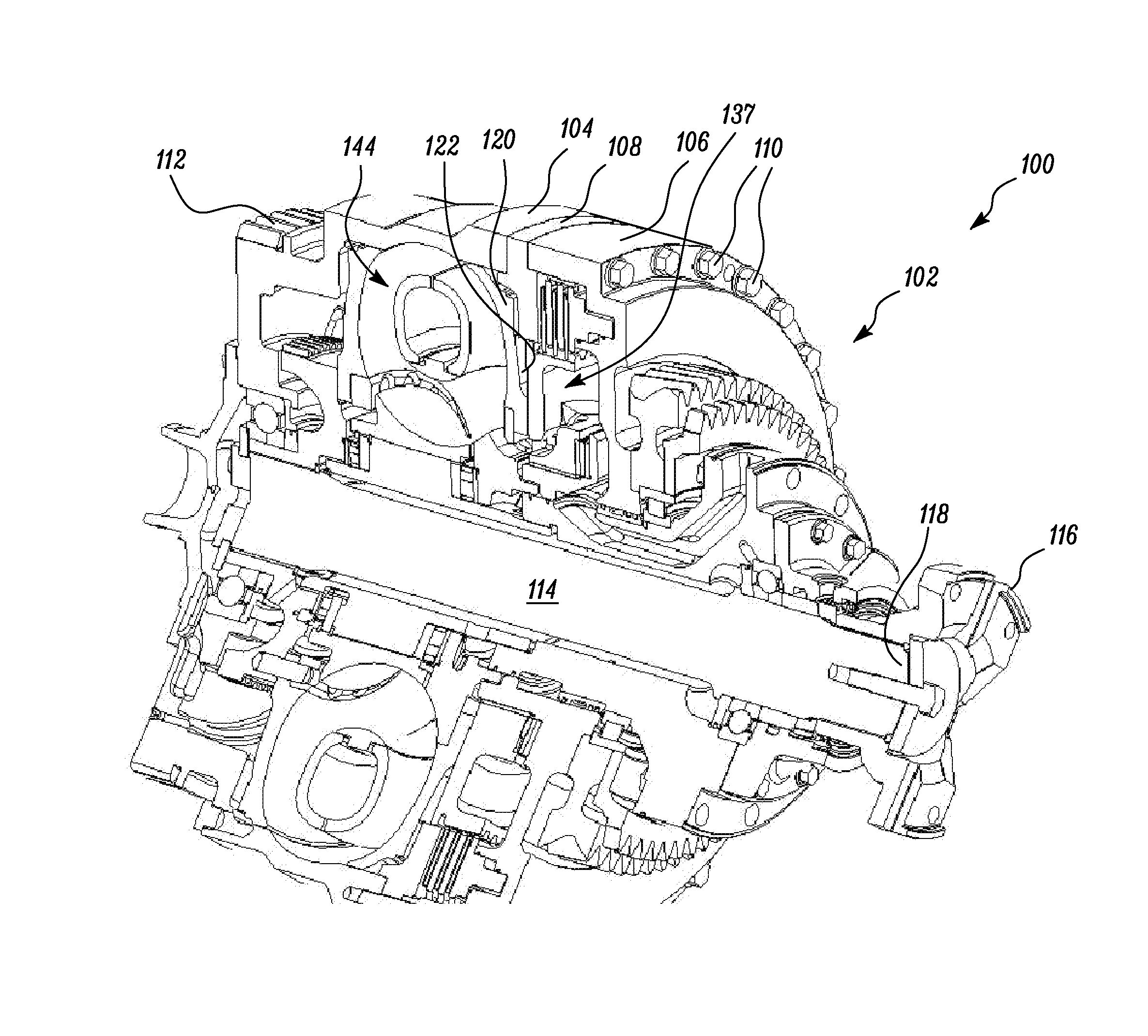
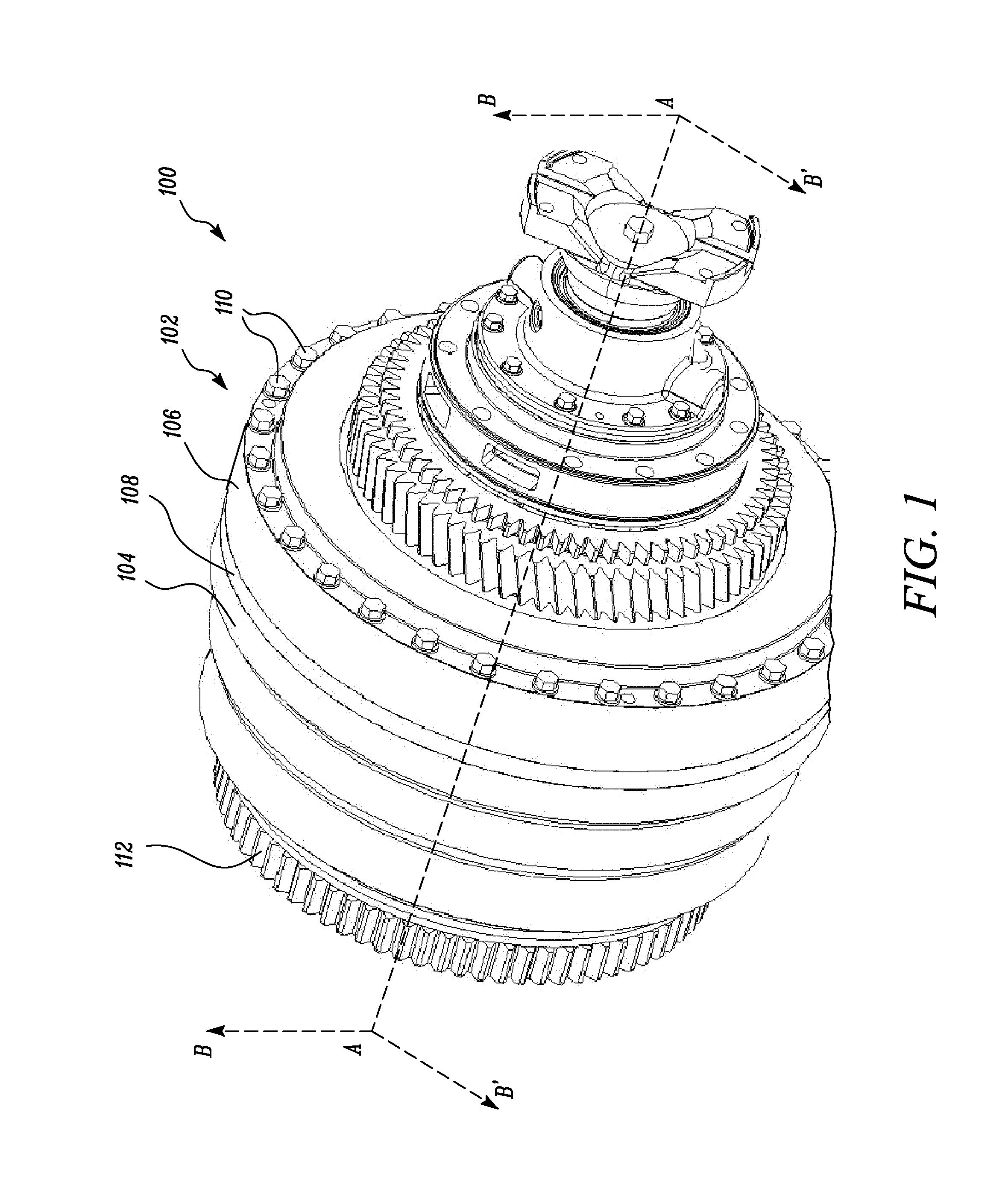
[0016]FIG. 1 illustrates a torque converter 100, in accordance with embodiments of the present disclosure. The torque converter 100 disclosed herein may be used in mobile machines for e.g., wheeled vehicles that are typically employed in various applications including, but not limited to, mining, quarrying, road construction, site preparation, etc. For example, the machine may be embodied in the f...


PUM


Abstract

A torque converter includes a housing, and an impeller shell disposed within the housing. The impeller shell has a back wall, and a plurality of fins radially arranged and extending outwardly from the back wall. The torque converter further includes a backing hub rigidly coupled to the back wall of the impeller shell. The backing hub has a barrier element extending therefrom. A free end of the barrier element is disposed proximal to the housing to restrict a flow of fluid therebetween.

Description

TECHNICAL FIELD[0001]The present disclosure relates to a torque converter. More particularly, the present disclosure relates to a torque converter having capabilities for cooling a clutch assembly present therein.BACKGROUND[0002]Earth moving machines have long been known to employ torque converters to co-operate with their engines. These torque converters typically contain impeller clutches having several sets of clutch plates and / or friction plates therein. These impeller clutches are typically configured for accomplishing a selective engagement between an impeller and a turbine present in the torque converter. However, these impeller clutches also have a propensity for heating up during operation i.e., when engaging and disengaging the impeller from the turbine numerous times during operation of the machine. Although various parts of the torque converter including the impeller clutch may dissipate heat through a natural process of convection via a body of the torque converter, flu...

Claims


Application Information

Patent Timeline
IPC IPC(8): F16H45/02F16H41/30F16H41/04
CPCF16H45/02F16H2045/0215F16H41/30F16H41/04F16H2045/0284F16D33/20
Inventor ROSS, VALERIE ANNETTELAN, XUEKUIWU, JIMRAO, QINYANGWATERS, TIMOTHY M.TIAN, WEIXUE
Owner CATERPILLAR INC
Why Eureka
Try Eureka