Multi-segment Optical Component and Related Optical Detecting Device Capable of Increasing SNR

a technology of optical detecting device and segmented optical components, applied in the direction of optical radiation measurement, instruments, lenses, etc., to achieve the effect of accurate detecting results and effective increase of the signal-to-noise ratio of optical detecting devices

Active Publication Date: 2017-03-02
PIXART IMAGING INC
View PDF1 Cites 3 Cited by
  • Summary
  • Abstract
  • Description
  • Claims
  • Application Information

AI Technical Summary

Benefits of technology

[0006]The present invention provides a multi-segment optical component capable of increasing signal-to-noise ratio and a related optical detecting device utilizing the multi-segment optical component for solving above drawbacks.
[0010]The present invention provides the innovative multi-segment optical component distinct from the conventional Fresnel lens. All the lateral lens portions of the multi-segment optical component have curvature radii different from the curvature radius of the central lens portion, and the curvature centers of all the lateral lens portions do not overlap the central axle of the central lens portion. Therefore, the multi-segment optical component can utilize the scattering isolation module to prevent the epidermal scattering signal from being transmitted toward the optical detecting component, and further utilize the optical collection module to collect the vessel scattering signal and / or the dermis scattering signal, so as to effectively increase the signal-to-noise ratio of the optical detecting device; the optical detecting device of the present invention can acquire accurate detecting result even through the external object does not directly contact an effective region (the working region, the touch region) of the optical detecting device.

Problems solved by technology

The conventional Fresnel lens 58 cannot overcome noise interference resulted from the epidermal scattering signal S1; therefore, design of an optical detecting device capable of effectively eliminating the epidermal scattering signal to increase detection accuracy is an important issue in the related optical detection industry.

Method used


Image

  • Multi-segment Optical Component and Related Optical Detecting Device Capable of Increasing SNR
  • Multi-segment Optical Component and Related Optical Detecting Device Capable of Increasing SNR
  • Multi-segment Optical Component and Related Optical Detecting Device Capable of Increasing SNR

Examples


Embodiment Construction

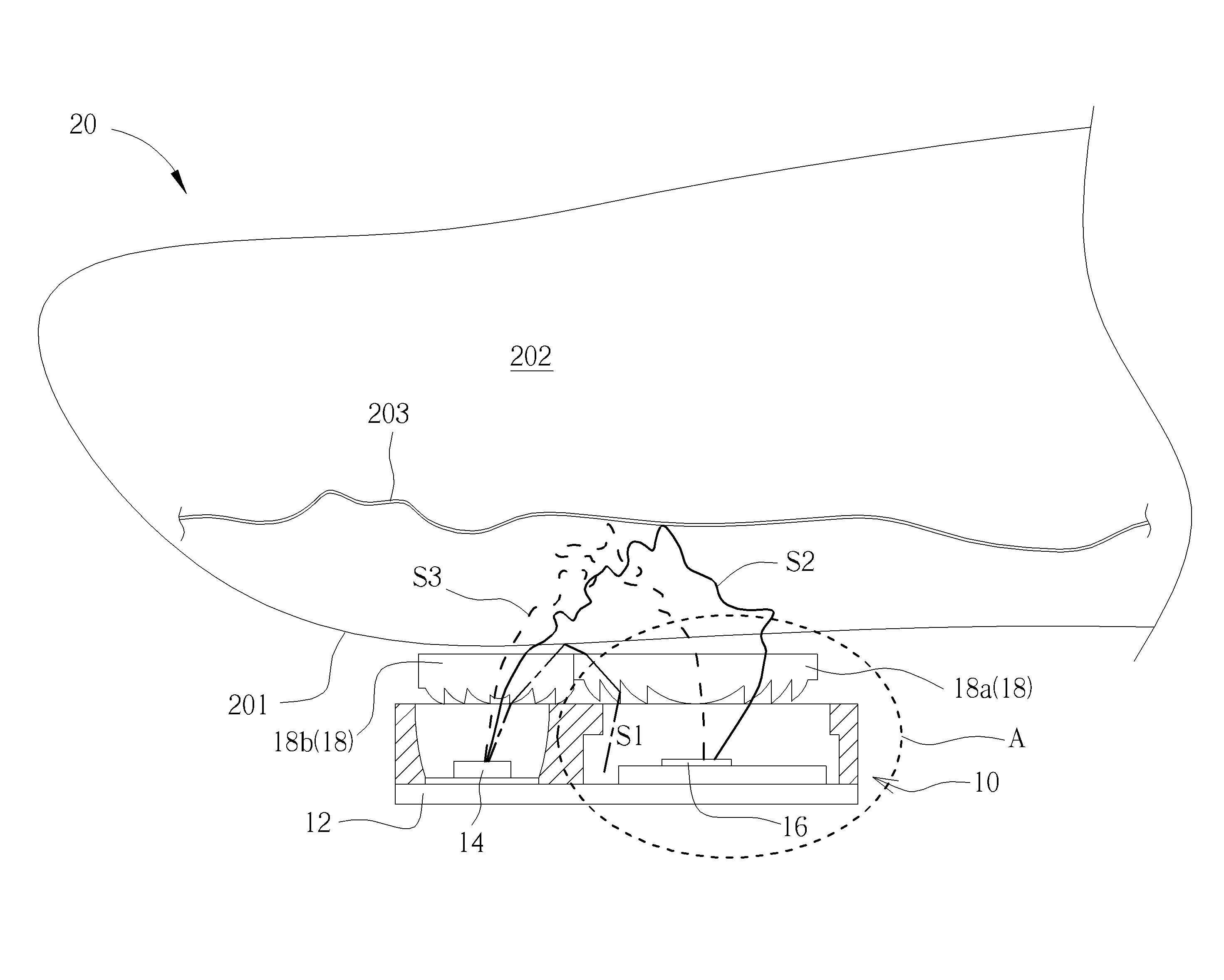
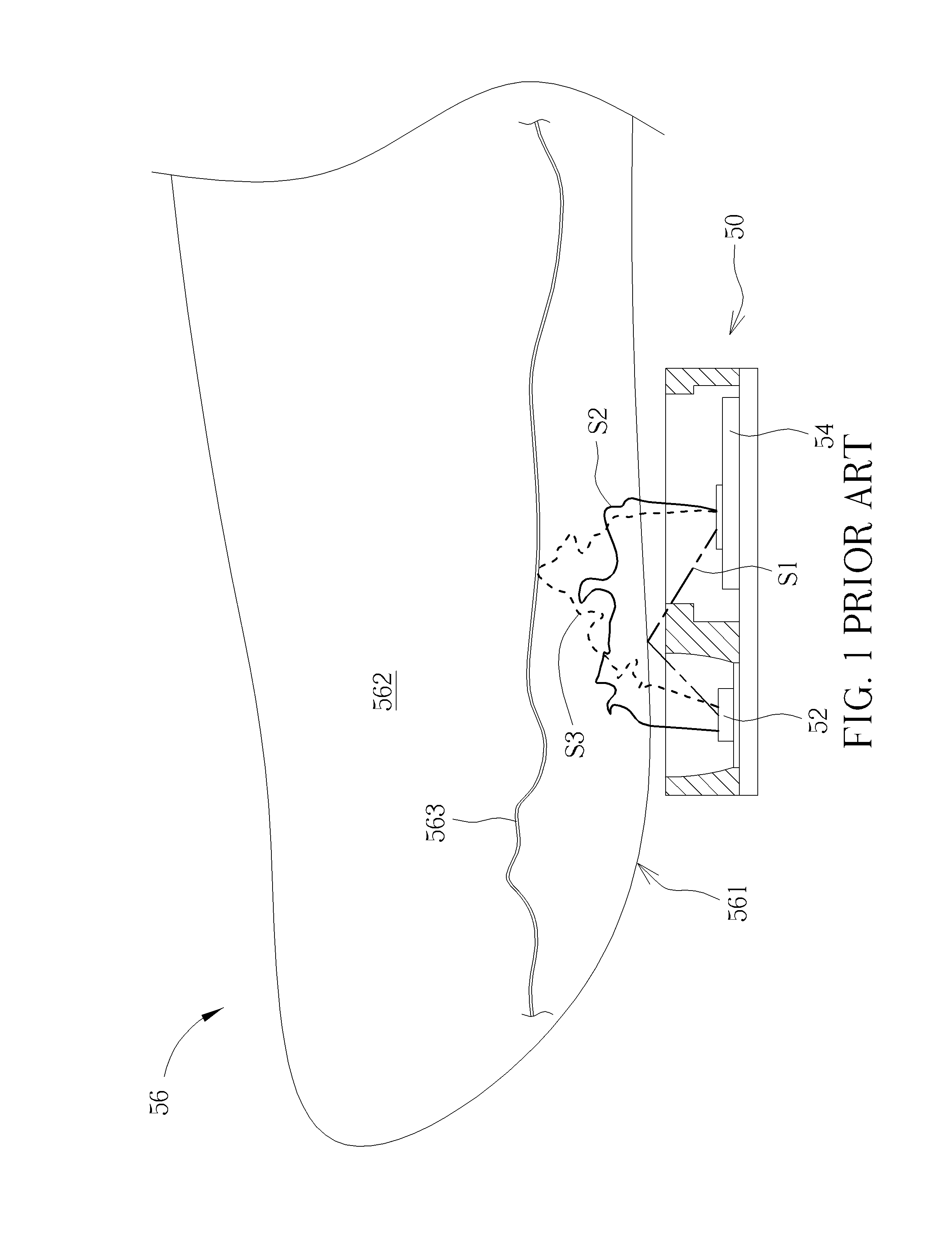
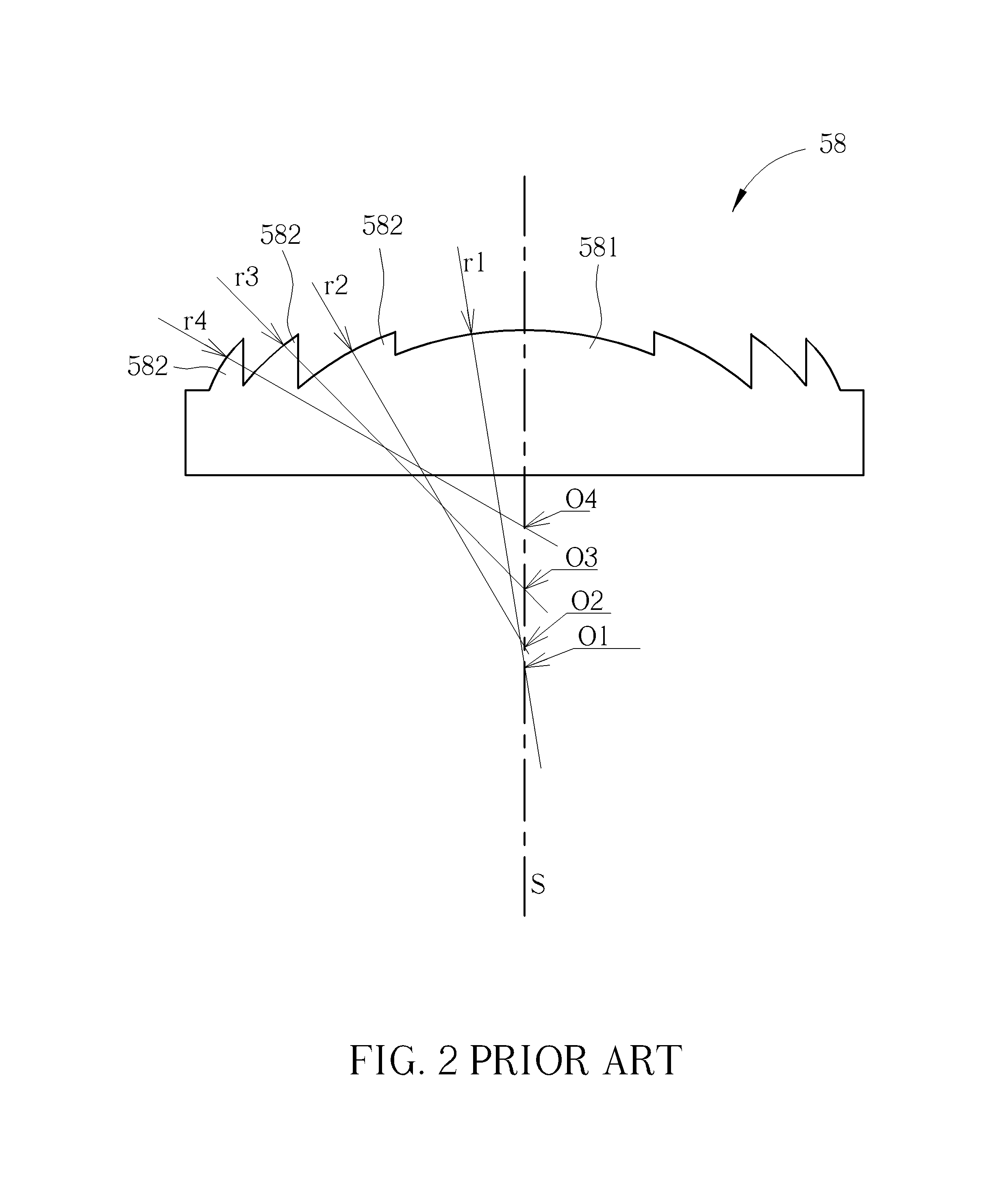
[0019]Please refer to FIG. 3 and FIG. 4. FIG. 3 is a diagram of an optical detecting device 10 according to an embodiment of the present invention. FIG. 4 is an enlarged diagram of the region A shown in FIG. 3. The optical detecting device 10 includes a substrate 12, a light emitting component 14, an optical detecting component 16 and a multi-segment optical component 18. The light emitting component 14 and the optical detecting component 16 are respectively disposed on different positions on the substrate 12. The light emitting component 14 faces outward of the optical detecting device 10 to project an optical detecting signal onto an external object 20. The optical detecting component 16 receives an optical reflecting signal from the external object 20, and analyzes information of the external object 20 according to photoplethysmography (PPG) of the optical signal. The external object 20 can be human skin, such as the finger or the wrist. The external object 20 may include an epid...


PUM

PropertyMeasurementUnit
signal-to-noise ratioaaaaaaaaaa
curvature radiusaaaaaaaaaa
curvatureaaaaaaaaaa

Abstract

A multi-segment optical component applied to increase signal-to-noise ratio includes a base, a central lens portion, an isolating lens portion and a collecting lens portion. The central lens portion is disposed on center of the base. The isolating lens portion is disposed by a side of the central lens portion, and the collecting lens portion is disposed by the other side of the central lens portion opposite to the isolating lens portion. At least one of the isolating lens portion and the collecting lens portion has a curvature radius different from a curvature radius of the central lens portion, and the curvature radius of the isolating lens portion can be similar to or different from the curvature radius of the collecting lens portion. The central lens portion has a central axle which does not overlap a curvature center of one of the isolating lens portion and the collecting lens portion.

Description

BACKGROUND OF THE INVENTION[0001]1. Field of the Invention[0002]The present invention relates to an optical detecting device utilizing an optical component to condense the light beam, and more particularly, to a multi-segment optical component capable of increasing signal-to-noise ratio and a related optical detecting device utilizing the multi-segment optical component.[0003]2. Description of the Prior Art[0004]Please refer to FIG. 1 and FIG. 2. FIG. 1 is a diagram of an optical detecting device 50 in prior art. FIG. 2 is a sectional view of a conventional Fresnel lens. The optical detecting device 50 utilizes a light emitting component 52 to output an optical detecting signal, the optical detecting signal is projected onto and reflected from an external object 56 to be received by an optical detecting component 54, and the optical detecting device 50 acquires information of the external object 56 by analyzing the reflected optical detecting signal. The external object 56 includes ...

Claims


Application Information

Patent Timeline
Patent Type & Authority Applications(United States)
IPC IPC(8): G02B19/00G02B3/08G01J1/08G01N21/47G01J1/04
CPCG02B19/0085G01N21/47G02B19/0009G01J1/08G02B3/08G01J1/0422A61B5/0059G01N21/474
Inventor HUANG, YU-HSIANGLAI, HUNG-CHING
Owner PIXART IMAGING INC
Why Eureka
Try Eureka