Wheel motor cooling system with equally divided flow

a cooling system and motor technology, applied in the direction of positive displacement liquid engines, machines/engines, vehicle sub-unit features, etc., can solve the problems of adding complexity, undesirable, controlling this power source, etc., and achieves the effect of minimizing space usage, simple and flexibl

Active Publication Date: 2017-03-02
FAIRFIELD MFG CO INC
View PDF0 Cites 2 Cited by
  • Summary
  • Abstract
  • Description
  • Claims
  • Application Information

AI Technical Summary

Benefits of technology

[0013]It is an object of the invention to provide a simple and flexible method for managing the cooling and lubricating system for vehicles incorporating one or more electric drive axles.
[0014]It is an object of the invention to provide an electric wheel motor cooling system which minimizes the usage of space near the wheel motors.

Problems solved by technology

To simplify the systems, the required pumps can be ganged together so that a single power source can be used, but providing this power source and controlling it adds complexity and is undesirable.

Method used


Image

  • Wheel motor cooling system with equally divided flow
  • Wheel motor cooling system with equally divided flow
  • Wheel motor cooling system with equally divided flow

Examples


Embodiment Construction

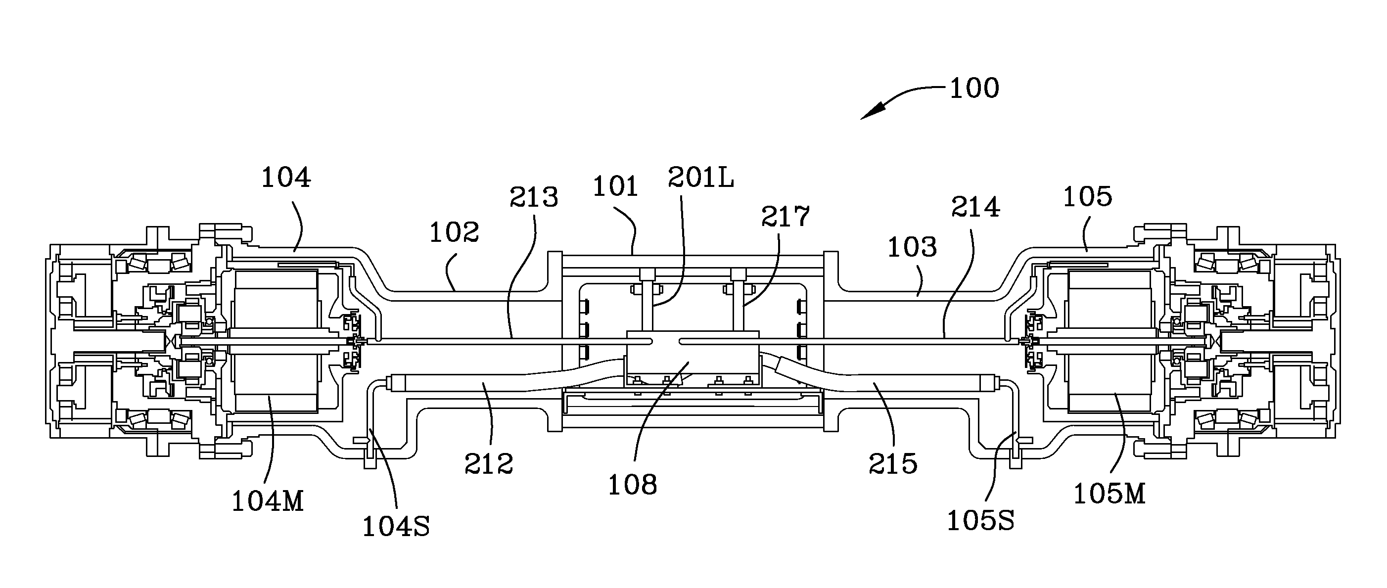
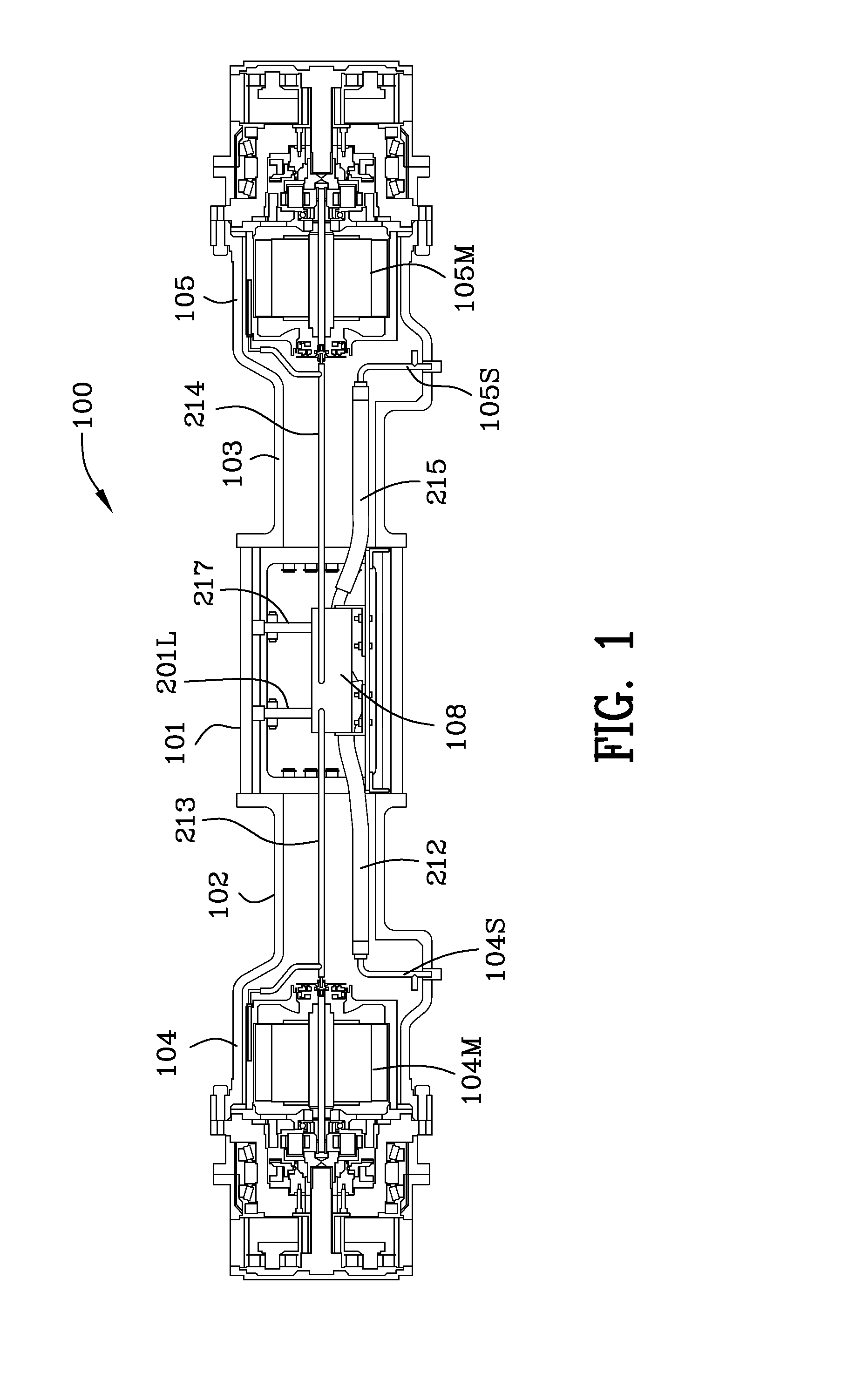
[0027]FIG. 1 is a schematic cross section 100 of an axle illustrating the scavenge sumps and the scavenge pumps for removal of the lubricating and cooling oil from the first wheel motor housing 104 and the second wheel motor housing 105. FIG. 1 illustrates centrally located housing 101 in an axle between the first wheel motor 104M and the second wheel motor 105M. Intermediate housing 102 resides between the centrally located housing 101 and the first wheel housing 104. Intermediate housing 103 resides between the centrally located housing 101 and the second wheel housing 105. First wheel housing 104 includes the first wheel motor 104M and the first wheel housing scavenge sump 104S. Second wheel housing 105 includes second wheel motor 105M and the second wheel housing scavenge sump 105S. Conduit 212 for conveying fluid from the sump 104S to the housing 108 for scavenge pumps 204, 205. Conduit 215 for conveying fluid from the sump 105S to the housing 108 for scavenge pumps 204, 205.

[0...


PUM


Abstract

An electric wheel motor cooling system includes first and second electric wheel motors and gear reducers which use hydraulic fluid for cooling and lubrication. Each of the electric wheel motor housings includes a sump and a scavenge pump for return of hydraulic fluid to the hydraulic fluid reservoir. A remotely located hydraulic pump interconnected with the hydraulic fluid reservoir supplies and powers first and second locally located hydraulic motors which supply the electric motors and gears with an equal flow of lubricating and cooling oil. The first and second hydraulic motors, in turn, drive a common output shaft which, in turn, drives first and second scavenge pumps. The first and second scavenge pumps have a higher fluid flow rate than the hydraulic motors ensuring that oil is removed from the first and second electric wheel motor housings thus eliminating any churning losses of the motors or gears.

Description

FIELD OF THE INVENTION[0001]The invention is in the field of wheel motors and gearboxes which drive an electric vehicle.BACKGROUND OF THE INVENTION[0002]Electric wheel drive systems used in off-highway machinery require a flow of coolant such as hydraulic oil to maintain an optimum operating temperature. Oil cooling is advantageous because it can provide both cooling and lubrication. Since churning losses can reduce efficiency, especially at higher speeds, dry sump systems are a preferred approach for implementing these cooling and lubrication systems.[0003]Implementation of a dry sump system in a simple form requires providing a supply and a scavenge pump at each wheel motor site and providing a means for powering these pumps. To simplify the systems, the required pumps can be ganged together so that a single power source can be used, but providing this power source and controlling it adds complexity and is undesirable.SUMMARY OF THE INVENTION[0004]The purpose of this invention is ...

Claims


Application Information

Patent Timeline
Patent Type & Authority Applications(United States)
IPC IPC(8): H02K9/193H02K7/102H02K7/116
CPCH02K9/193H02K7/102H02K7/116F16H57/0412F16H57/0441B60Y2306/03B60K7/0007B60K11/02B60K17/043B60K2001/006B60K2007/0038B60K2007/0092B60Y2200/142B60Y2200/20B60Y2200/41F04B17/03F16H57/042F16H2057/02034
Inventor CARON, LAVERNE ANDREWZHANG, SHUOMEARS, KEITH
Owner FAIRFIELD MFG CO INC
Why Eureka
Try Eureka