Tubular connector with an automatic connection

a technology of automatic connection and tubular coupling, which is applied in the direction of adjustable joints, pipe joints, sleeves/socket joints, etc., can solve the problems of increased manufacturing costs of tubular couplings, complex drive coordination between, and less robustness

Active Publication Date: 2017-03-09
A RAYMOND & CO
View PDF0 Cites 20 Cited by
  • Summary
  • Abstract
  • Description
  • Claims
  • Application Information

AI Technical Summary

Benefits of technology

[0017]An object of the invention is thus to mitigate the above-indicated drawbacks.

Problems solved by technology

Firstly, it requires a plurality of separate parts that interact with one another to achieve the retaining or locking of the male connector in the female connector and the automatic movement of the connection element towards the inside of the female connector.
These various parts require complex drive co-ordination between them.
They also increase the costs of manufacturing the tubular coupling.
The tubular coupling also has a body that has many through openings that make it less robust.
In addition, the stroke of the connection element, after going past the collar, depends on the magnitude of the deformation of the tongue, and, in practice, that stroke is relatively short due to the miniaturization of the parts.
As a result, the difference between the pre-assembly high position and the low position of the connection element is small, and so that difference is difficult to perceive, either visually or by touch.

Method used


Image

  • Tubular connector with an automatic connection
  • Tubular connector with an automatic connection
  • Tubular connector with an automatic connection

Examples


Embodiment Construction

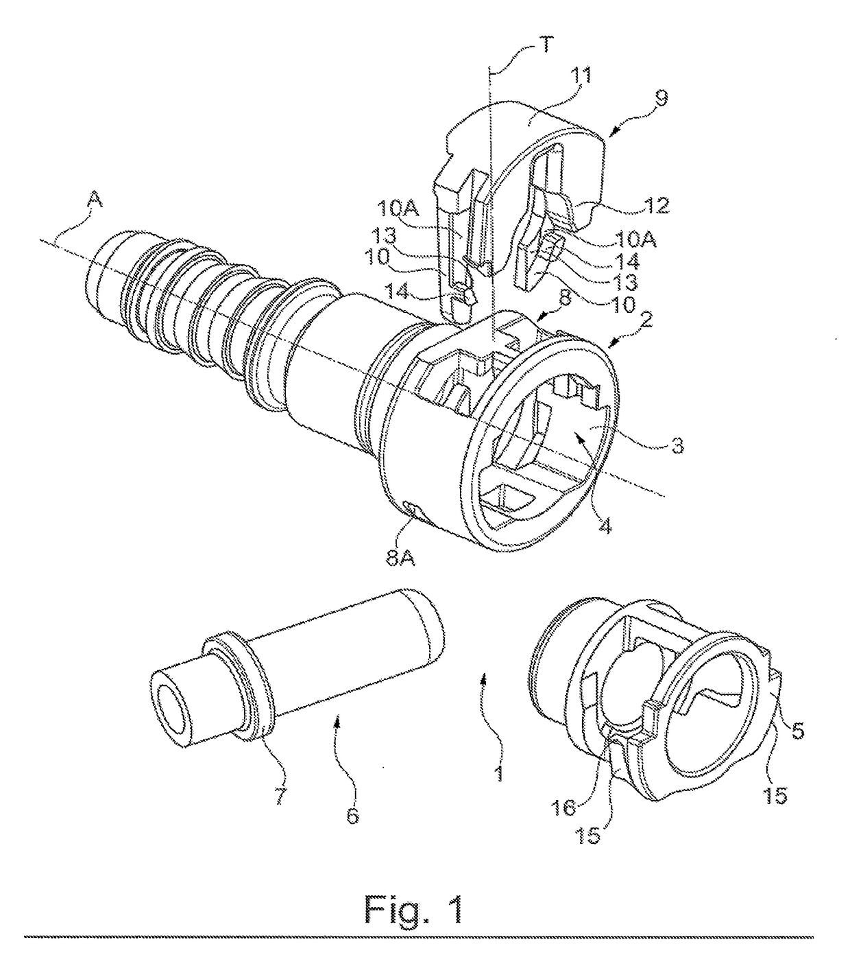
[0041]As can be seen in FIG. 1, the tubular coupling of the invention includes a female tubular end-piece (female connector) 2, which, in this example, is in two portions comprising a tubular main body 3 that extends in an axial direction A, and that is provided with an axial opening 4, and a ring 5 that is suitable for being axially engaged by interfitting into the opening 4 in the main body 3.

[0042]It is understood that the invention extends to include a female end-piece that is in one piece or that forms an integrally molded part.

[0043]In the tubular coupling 1, a male connection tubular end-piece (male connector) 6 is provided for being inserted axially into the female connector, and, in this example, into the ring 5 thereof.

[0044]The male connector 6 is in the form of an elongate cylindrical tube and has an annular collar 7 around its circular periphery, the diameter of the annular collar 7 being slightly less than the inside diameter of the ring 5. As can also be seen in FIG. ...


PUM


Abstract

A tubular coupling comprising a female connector (2) into which a male connector (6) provided with an annular collar (7) is designed to be inserted axially, and a connection element (9) that extends in a transverse direction in the female connector. The connection element is designed to interfere mechanically with the collar while the male connector is being inserted into the female connector, and to move by itself in said transverse direction towards the inside of the female connector. In addition, the connection element and the female connector are also designed so that, after the reaction to the radial resilient deformation of the connection element on the collar of the male connector, they come to bear against each other in the manner of a projection (14) that, by resilient return, exerts pressure on a guide ramp (15), so as to generate a thrust force that extends the movement of the connection element towards the inside of the female connector.

Description

TECHNICAL FIELD[0001]The present invention relates to the field of tubular couplings for connecting fluid pipes or ducts, e.g. fuel hoses for motor vehicles.[0002]More particularly, the invention relates to a tubular coupling comprising a female connector into which a male connector provided with an annular collar is designed to be inserted axially, and a connection element that extends in a transverse direction in the female connector and that is designed to be deformed resiliently and radially towards the outside of the female connector by mechanically interfering with said collar while the male connector is being inserted into the female connector, and, in reaction to this radial resilient deformation, to move by itself in said transverse direction towards the inside of the female connector.PRIOR ART[0003]Such a tubular coupling for coupling hoses is already known, in particular from Patent Document US 2012 / 0326435.[0004]In that known tubular coupling, the connection element cons...

Claims


Application Information

Patent Timeline
Patent Type & Authority Applications(United States)
IPC IPC(8): F16L37/088
CPCF16L2201/10F16L37/088F16L21/08F16L27/08F16L37/0885F16L37/144
Inventor CHAUPIN, JEROMEPOGGI, FREDERIC
Owner A RAYMOND & CO
Why Eureka
Try Eureka