Handle assembly for a vacuum cleaner

a technology for vacuum cleaners and handles, applied in the direction of suction handles, suction hoses, cleaning equipment, etc., can solve the problems of difficult manoeuvre of the cleaner head, and achieve the reduction of the restriction of the movement of the handle by the hose, the relative compact arrangement, and the large angle

Active Publication Date: 2017-03-16
DYSON TECH LTD
View PDF16 Cites 7 Cited by
  • Summary
  • Abstract
  • Description
  • Claims
  • Application Information

AI Technical Summary

Benefits of technology

[0010]A first end of the duct assembly may extend along a first axis, and a second opposite end of the duct assembly may extend along a second axis. The first duct may then be free to pivot to a position in which the first axis is parallel to the second axis. Consequently, when a hose is attached to the first end and an elongate tube is attached to the second end of the duct assembly, the hose is free to pivot to a position in which the hose extends alongside the elongate tube. This then has the advantage of providing a relative compact arrangement when the handle assembly is not in use.
[0011]The pivot axis may be located below the handle, and the arcuate section of the second duct may arc upwardly into the space between the handle and the pivot axis. By arcing upwardly into the space beneath the handle, the arcuate sections of the duct assembly are able to subtend relatively large angles without increasing excessively the height of the handle assembly.
[0012]The first duct and the second duct may rotate collectively relative to the handle. In particular, the first duct and the second duct may rotate collectively about a rotation axis that is orthogonal to the pivot axis. Consequently, when a hose is attached to the duct assembly, the handle assembly provides two degrees of freedom in the movement of the hose relative to the handle. In particular, the hose is free to pivot relative to the handle about the pivot axis, and the hose is free to rotate relative to the handle about the rotation axis. By providing two degrees of freedom, restriction in the movement of the handle by the hose is further reduced.
[0013]The duct assembly may comprise a third duct to which the handle is fixedly attached. The second duct may then be rotatably attached to the third duct. This then has the advantage that the handle may be used to better control the orientation of an attachment without undue interference from the hose. For example, by rotating the handle about the rotation axis, the orientation of an attachment attached to the third duct may be changed. As the handle rotates, the weight of a hose attached to the first duct will cause the first and second ducts to rotate relative to the handle about the rotation axis. The net result is that the first and second ducts remain stationary as the handle rotates, and thus the hose does not interfere with or impede the movement of the handle.
[0014]The second duct may be a double-walled duct comprising an inner tube and an outer tube, and pivoting the first duct relative to the second duct may cause the first duct to move between the inner tube and the outer tube. Consequently, when the second duct is located upstream of the first duct, air flowing through the duct assembly moves from the smaller diameter inner tube to the larger diameter first duct. This then has the advantage that the end of the first duct does not present a shoulder to the oncoming flow of air, which would otherwise increase turbulence and thus flow losses and noise. By providing an outer tube in addition to an inner tube, the handle may be attached to the second duct without inhibiting or otherwise restricting the pivoting movement of the first duct.

Problems solved by technology

Unfortunately, the hose often restricts or impedes movement of the handle assembly, thus making it difficult to manoeuvre the cleaner head.

Method used


Image

  • Handle assembly for a vacuum cleaner
  • Handle assembly for a vacuum cleaner
  • Handle assembly for a vacuum cleaner

Examples


Embodiment Construction

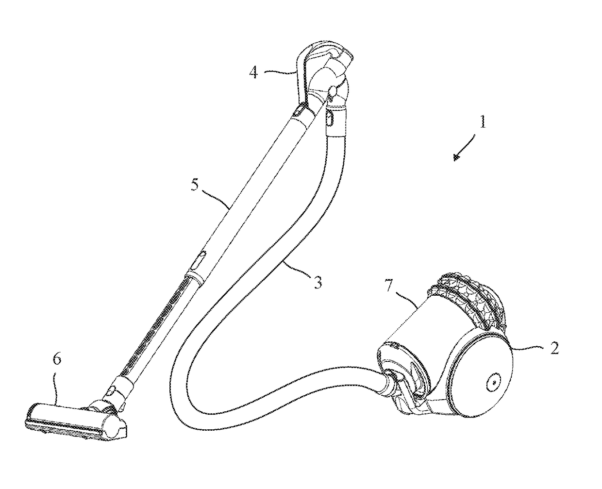
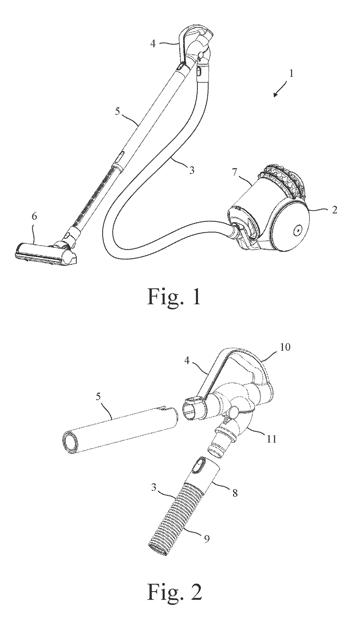
[0029]The vacuum cleaner 1 of FIG. 1 comprises a main body 2, a hose 3, a handle assembly 4, an elongate tube 5, and a cleaner head 6. The main body 2 comprises a dirt separator 7 and a vacuum motor (not shown). The hose 3 is attached at one end to the main body 2 and at an opposite end to the handle assembly 4. The elongate tube 5 is attached at one end to the handle assembly 4 and at an opposite end to the cleaner head 6. During use, the vacuum motor generates suction that causes dirt-laden air to be drawn in through an opening in the cleaner head 6. From the cleaner head 6, the dirt-laden air is carried to the dirt separator 7 via the elongate tube 5, the handle assembly 4 and the hose 3. The handle assembly 4 is then used to manoeuvre the cleaner head 6 over the cleaning surface.

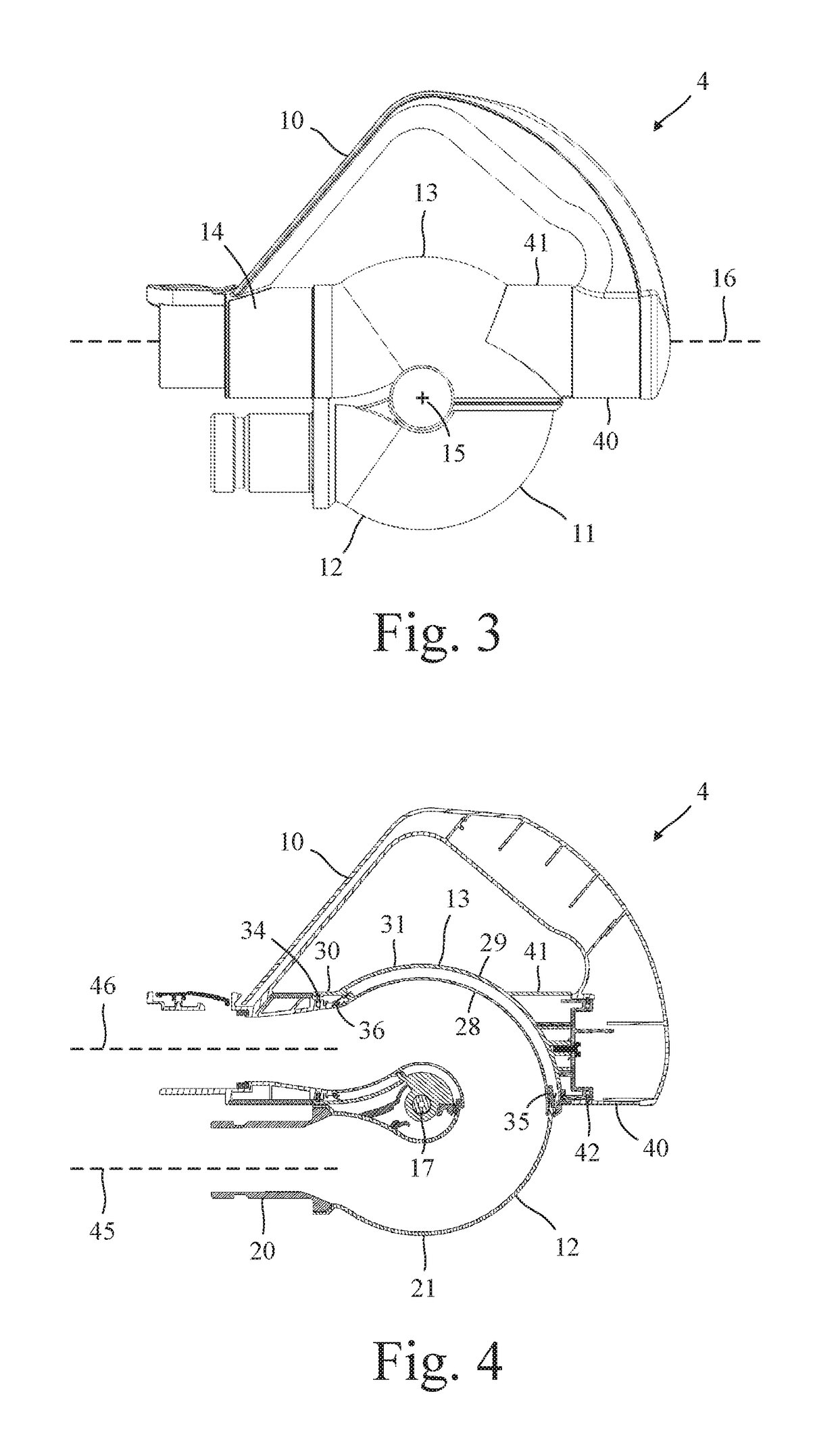
[0030]Turning now to FIGS. 2 to 8, the handle assembly 4 comprises a handle 10 attached to a duct assembly 11. The hose 3 of the vacuum cleaner is then removably attached to a first end of the duct assem...


PUM


Abstract

A handle assembly for a vacuum cleaner that includes a handle attached to a duct assembly. The duct assembly includes a first duct and a second duct, and the first duct pivots relative to the second duct about a pivot axis. The first duct and the second duct each have an arcuate section that arcs about the pivot axis. Pivoting the first duct relative to the second duct then causes the arcuate section of one of the ducts to move in and out of the arcuate section of the other of the ducts.

Description

REFERENCE TO RELATED APPLICATION[0001]This application claims priority of United Kingdom Application No. 1516181.3, filed Sep. 14, 2015, the entire contents of which are incorporated herein by reference.FIELD OF THE INVENTION[0002]The present invention relates to a handle assembly for a vacuum cleaner.BACKGROUND OF THE INVENTION[0003]The handle assembly of a vacuum cleaner may comprise a duct through which dirt-laden air is carried. One end of the duct may be attached to a hose, which in turn is attached to a main body of the vacuum cleaner. The other end of the duct may be attached to an elongate tube, which in turn is attached to a cleaner head. During use, the handle assembly is used to manoeuvre the cleaner head over a surface to be cleaned. Unfortunately, the hose often restricts or impedes movement of the handle assembly, thus making it difficult to manoeuvre the cleaner head.SUMMARY OF THE INVENTION[0004]The present invention provides a handle assembly for a vacuum cleaner, t...

Claims


Application Information

Patent Timeline
Patent Type & Authority Applications(United States)
IPC IPC(8): A47L9/32A47L9/24A47L5/36
CPCA47L9/327A47L9/24A47L5/36A47L9/242A47L9/322A47L5/225A47L9/325
Inventor MILLINGTON, DAVID ALANBOX, CHARLES GEOFFREY
Owner DYSON TECH LTD
Why Eureka
Try Eureka