Hydro-mechanical autografting tool and method of use

a technology of autografting and hydraulic force, applied in the field of rotary osteotomy, can solve the problems of affecting the treatment of mandibular site, affecting the healing effect of osteotomy, and the location of the bone may be wholly unsuitable for the violent impact of osteotomy, so as to achieve the effect of managing the expansion rate and enlarge the osteotomy

Inactive Publication Date: 2017-03-16
HUWAIS IP HLDG
View PDF2 Cites 5 Cited by
  • Summary
  • Abstract
  • Description
  • Claims
  • Application Information

AI Technical Summary

Benefits of technology

[0022]FIG. 7 is a simplified cross-sectional view showing a surgical procedure referred to herein as “bounce” where an osteotome according to the present invention is repeatedly pushed into the osteotomy and...

Problems solved by technology

Treatment of a mandibular site, for example, is often limited due to the increased density and reduced plasticity exhibited by the bone in this region.
Other non-dental bone implant sites may have similar challenging density and plasticity characteristics.
Or, the location of the bone may be wholly unsuitable for the violent impact of an osteotome, such as in small bone applications like the vertebrae and hand/wrist areas to name a few.
Additionally, since the traditional osteotome is inserted by hammering, the explosive nature of the percussive force provides limited control over the expansion process, which often leads to unintentional displacement or fracture such as in the labial plate of bone in dental applications.
The often rapid expansion rate caused by a hammered osteotome subjects the bone structure to stress spikes that exceed the bone's ultimate tensile strength and produces unwanted cracks.
Many patients do not tolerate the osteotome technique well, frequently complaining about the impact from the surgical mallet.
Fu...

Method used


Image

  • Hydro-mechanical autografting tool and method of use
  • Hydro-mechanical autografting tool and method of use
  • Hydro-mechanical autografting tool and method of use

Examples


Embodiment Construction

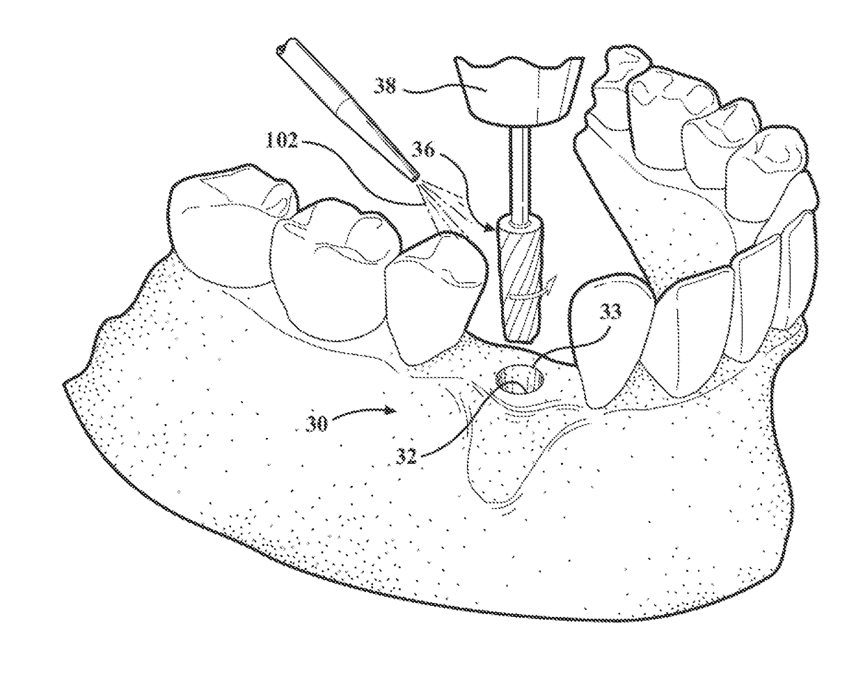
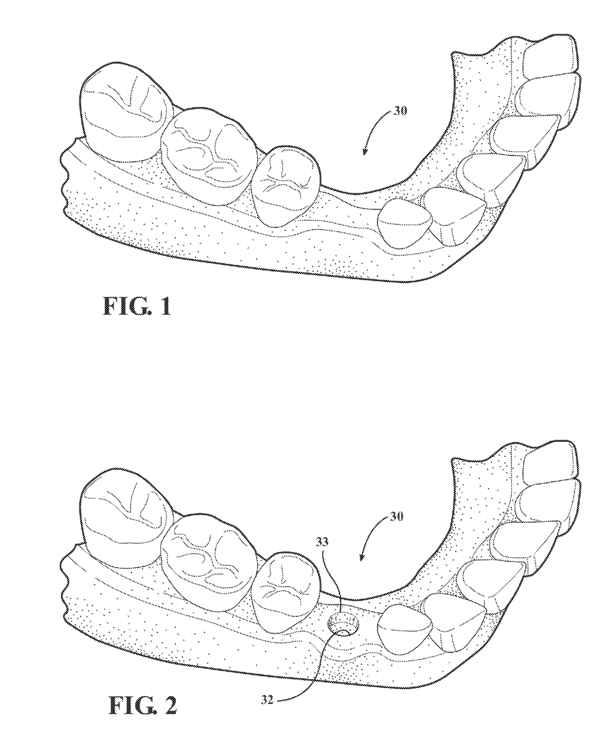
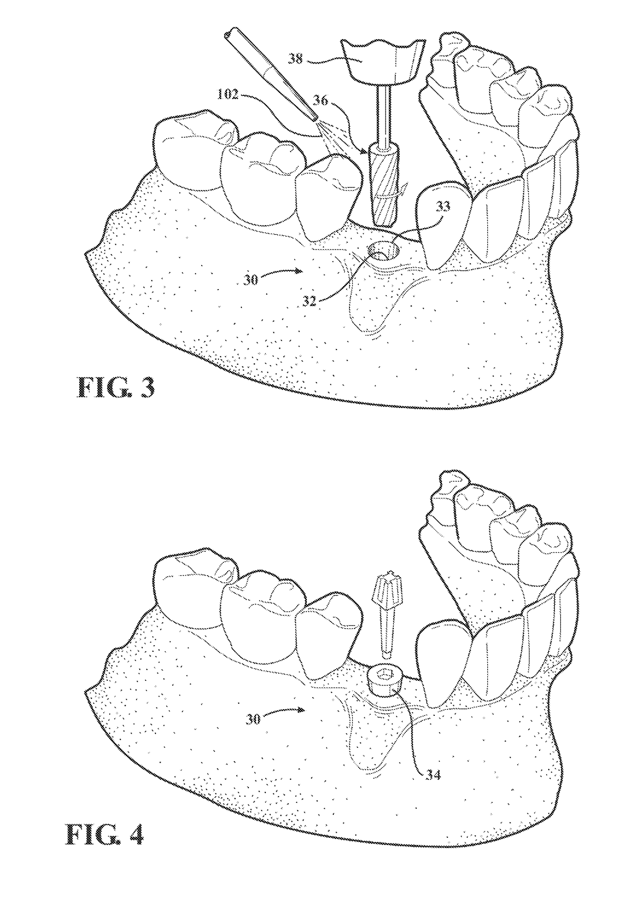
[0051]Referring to the figures, wherein like numerals indicate like or corresponding parts throughout the several views, FIGS. 1-4 show the example of a dental implant, in which preparation of an osteotomy is required to receive a bone implant (FIG. 4). It will be understood that this invention is not limited to dental applications, but may be applied across a wide spectrum of orthopedic applications. Furthermore, the invention is not even limited to bone applications, but may be used to prepare holes in other solid and cellular materials for industrial and commercial applications, to name but a few. In FIG. 1, an edentulous (without teeth) jaw site 30 is shown that needs expanded and prepared as an osteotomy 32 (FIG. 2) in order to receive an implant 34 (FIG. 4) or other fixture device. The series of steps include first boring a pilot hole into the recipient bone to form the initial osteotomy (not shown), then incrementally expanding the osteotomy using progressively wider rotary e...


PUM


Abstract

Methods and tools for expanding a precursor hole in a host material to receive an anchor or fixture. The precursor hole is enlarged by a rotary tool having helical flutes and interposed lands. The lands each have a working edge that densities bone when the tool is rotated in a non-cutting direction. When the tool is used with a copious wash of irrigating fluid, hydraulic pressure builds inside the precursor hole. The operator can modulate the hydraulic pressure by axially stroking the rotating tool. The working edges sweep against the interior surface of the hole to gently expand its diameter by incremental plastic deformations with little to no removal of host material. The host material may be bone and the hole formed may be an osteotomy that is prepared with dense, compacted sidewalls to receive a bone implant with a high degree of primary stability.

Description

CROSS REFERENCE TO RELATED APPLICATIONS[0001]This application claims priority to Provisional Patent Application No. 61 / 953,415 filed Mar. 14, 2014, and also claims priority to Provisional Patent Application No. 62 / 007,811 filed Jun. 4, 2014, the entire disclosures of which are hereby incorporated by reference and relied upon.BACKGROUND OF THE INVENTION[0002]Field of the Invention[0003]The invention relates generally to methods for preparing a hole to receive an anchor or fixture in any host material, and in one embodiment the invention more specifically relates to a rotary osteotome and methods implemented thereby for expanding an osteotomy with dense, compacted sidewalls to receive an implant or fixation device.[0004]Description of Related Art[0005]An implant is a medical device manufactured to replace a missing biological structure, to support a damaged biological structure, or to enhance an existing biological structure. Bone implants are implants of the type placed into the bone...

Claims


Application Information

Patent Timeline
IPC IPC(8): A61C8/00A61C1/00
CPCA61C8/0089A61C2008/0084A61C1/0061A61C8/0033A61B17/1615
Inventor HUWAIS, SALAH
Owner HUWAIS IP HLDG
Why Eureka
Try Eureka