Autografting osteotome

a technology of osteotomy and autograft, which is applied in the field of tools, can solve the problems of limiting the treatment of mandibular sites, affecting the osseointegration of the bone, and the location of the bone may be wholly unsuitable for the violent impact of the osteotomy, so as to promote osseointegration and expand the osteotomy

Active Publication Date: 2016-05-03
HUWAIS IP HLDG
View PDF47 Cites 28 Cited by
  • Summary
  • Abstract
  • Description
  • Claims
  • Application Information

AI Technical Summary

Benefits of technology

[0016]According to one aspect of this invention, a rotary osteotome is configured to be turned in one direction to enlarge an osteotomy by burnishing. The rotary osteotome includes a shank having an elongated cylindrical shaft. A body joined is to the shank. The body has an apical end remote from the shank, and a conically tapered profile decreasing from a maximum diameter adjacent the shank to a minimum diameter adjacent the apical end. The apical end includes at least one lip. A plurality of flutes are disposed about the body. Each flute has a burnishing face and an opposing cutting face. A land is formed between adjacent flutes. The lip is configured to simultaneously auto-graft and compact bone (i.e., gently push osseous structure laterally outwardly in a condensation mechanism) when continuously rotated at high speed in a burnishing direction and concurrently forcibly advanced into an osteotomy. The auto-grafting and compaction action of the lip enable the rotary osteotome to expand an osteotomy from top to bottom in a progressive manner while retaining the beneficial properties of immediately grafting displaced bone material directly into the osteotomy, and thereby promoting osseointegration of a subsequently placed implant or fixation member.
[0017]According to another aspect of this invention, a rotary tool is configured to be turned continuously in one direction to enlarge a hole in cellular material (i.e., not limited to bone) by burnishing. The rotary tool includes a shank that establishes a longitudinal axis of rotation for the rotary tool. A body is joined to the shank. The body has an apical end remote from the shank, and a conically tapered profile decreasing from a maximum diameter adjacent the shank to a minimum diameter adjacent the apical end. The apical end includes at least one lip. A plurality of flutes are disposed about the body. Each flute has a burnishing face and an opposing cutting face. A land is formed between adjacent flutes. Each land has a land face joining a burnishing face of one the flute and a cutting face of an adjacent flute. At least one of the lip and the lands are configured to generate an opposing axial reaction force when continuously rotated in a burnishing direction and concurrently forcibly advanced into a hole. The push-back phenomenon gives the user enhanced control over the expansion procedure, and effective decouples the rotation of the tool to the rate of expansion of the hole.

Problems solved by technology

Treatment of a mandibular site, for example, is often limited due to the increased density and reduced plasticity exhibited by the bone in this region.
Other non-dental bone implant sites may have similar challenging density and plasticity characteristics.
Or, the location of the bone may be wholly unsuitable for the violent impact of an osteotome, such as in small bone applications like the vertebrae and hand / wrist areas to name a few.
Additionally, since the traditional osteotome is inserted by hammering, the explosive nature of the percussive force provides limited control over the expansion process, which often leads to unintentional displacement or fracture such as in the labial plate of bone in dental applications.
Many patients do not tolerate the osteotome technique well, frequently complaining about the impact from the surgical mallet.
Thus, the rate of bone expansion is a direct and unalterable function of the rate at which the surgeon turns the expander tool, and the surgeon is unable to vary other parameters such as pressure and / or rotation rate to achieve an optimum expansion rate.
This inexorable linking of tool rotation rate to bone expansion rate in all prior art rotary expander systems limits surgical control over the implant process, and in some cases may lead to unnecessary patient discomfort.
One significant disadvantage of the current approaches to improving osseointegration, namely the use of cements and implant constructions, is the relatively high added cost.

Method used


Image

  • Autografting osteotome
  • Autografting osteotome
  • Autografting osteotome

Examples


example

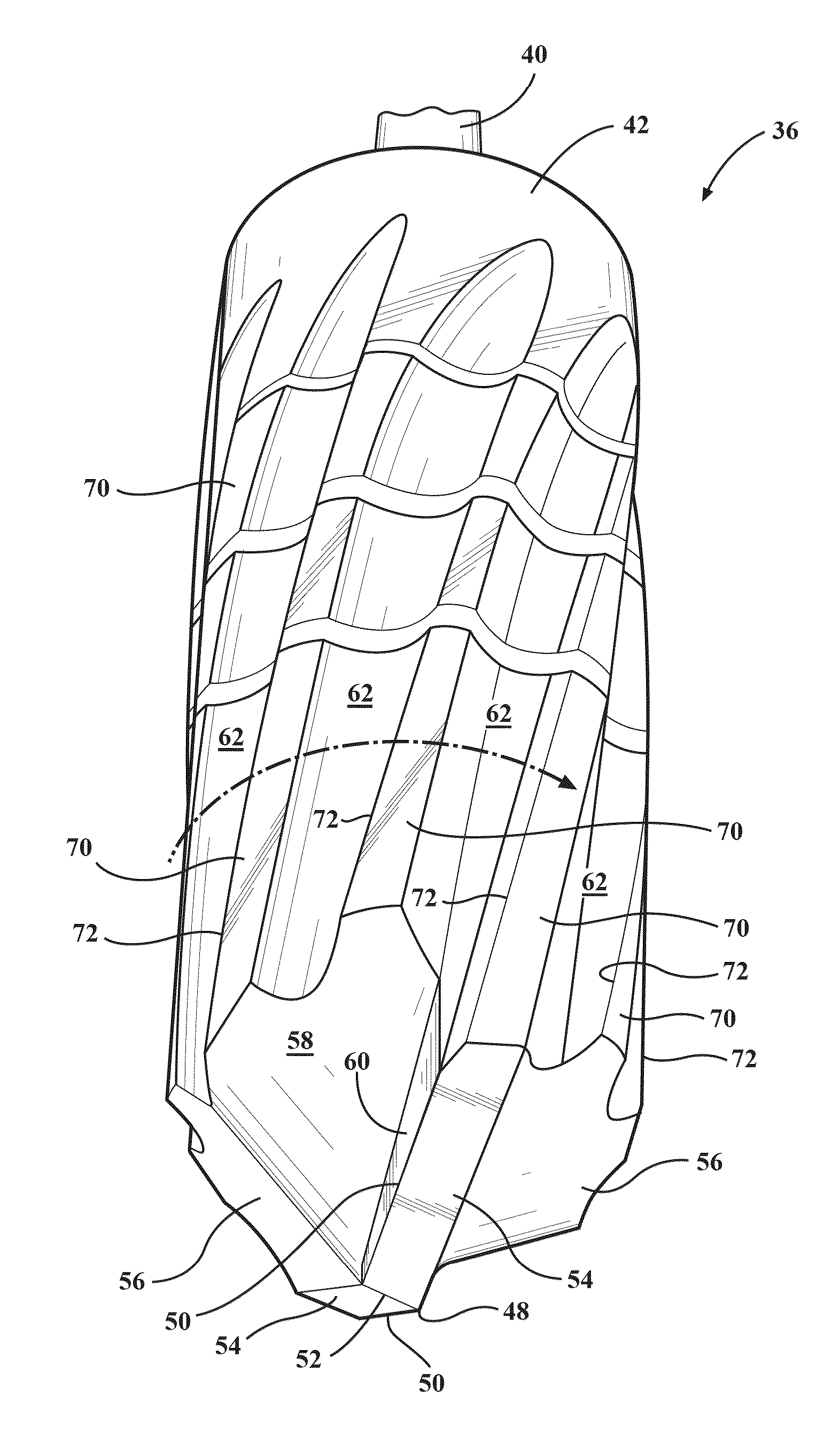
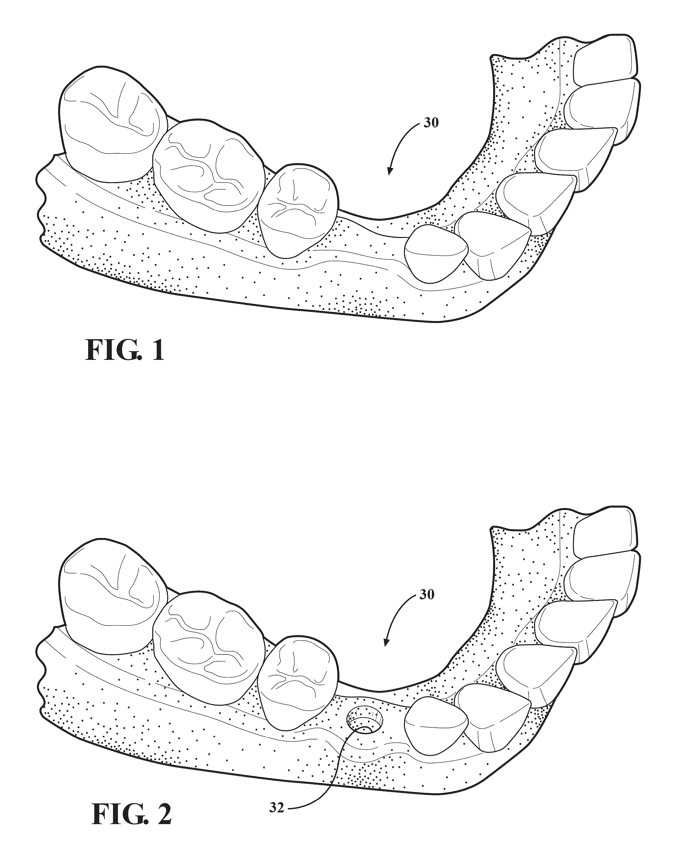
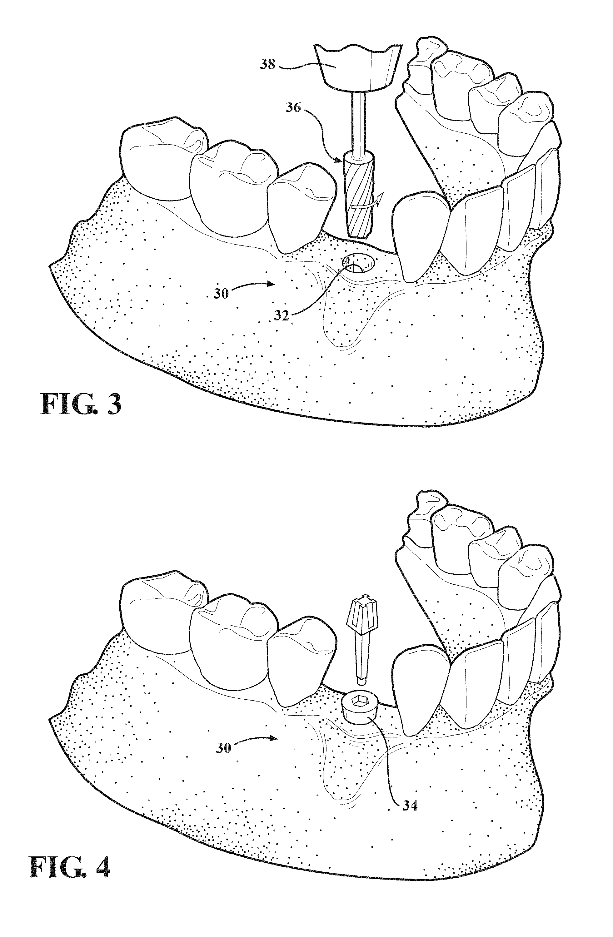
[0085]The mechanical tests were conducted with a surgical drill motor 38 and materials testing machine to control the rotary speed and depth penetration rate while measuring force and torque during drilling / burnishing procedures in bone. In other words, the manual influence of a surgeon was not involved in the following test report. The procedures using a prior art burr drill, fluted osteotome 36 in “Burnishing Mode” (Burnishing Osteotome), and fluted osteotome 36 in “Drilling Mode” (Osteotome Drill) were compared for insertion and removal torque of a 3.8 mm or 6.0 mm implant 34. Heat generation was measured during the drilling procedure by inserting a thermocouple into the bone, 1 mm away from the edge of the hole. Procedures included, drilling (900 RPM) without irrigation and burnishing (200, 400, 600, 900, and 1100 RPM), with and without irrigation. The implant 34 stability was also measured with the Osstell resonance frequency analysis system. The morphology of bone around the h...


PUM


Abstract

A fluted osteotome is rotated in one direction to enlarge an osteotomy by burnishing, and by cutting / drilling when turned in an opposite direction. A conically tapered body has an apical end with lips. The lips are set to grind bone when rotated in the burnishing direction and cut bone when turned in the cutting / drilling direction. Helical flutes and interposed lands are disposed about the body. The flutes each have a working edge that burnishes bone when rotated in the burnishing direction and cuts bone when turned in the cutting / drilling direction. The lips and lands generate an opposing axial reaction force that improves surgical control. The osteotome auto-grafts bone by reapplying ground particles in a compacted manner along the entire depth of the osteotomy, particularly at the bottom.

Description

CROSS REFERENCE TO RELATED APPLICATIONS[0001]This application is a Continuation of PCT / US13 / 55539, filed Aug. 19, 2013, published as WO 2014 / 077920, which in turn claims priority to Provisional Patent Application No. 61 / 727,849 filed Nov. 19, 2012. This application is also a continuation-in-part of U.S. Ser. No. 13 / 608,307 filed Sep. 10, 2012, published as US 2013 / 0004918, which is a continuation-in-part of U.S. Ser. No. 13 / 427,391 filed Mar. 22, 2012, published as US 2012 / 0244497, which claims priority to Provisional Patent Application No. 61 / 466,579 filed Mar. 23, 2011. The entire disclosures of each priority document are hereby incorporated by reference and relied upon.BACKGROUND OF THE INVENTION[0002]1. Field of the Invention[0003]The invention relates generally to tools for preparing a hole to receive an implant or fixture, and more particularly to rotary osteotomes and methods implemented thereby for expanding an osteotomy or hole in cellular material to receive an implant or ...

Claims


Application Information

Patent Timeline
Patent Type & Authority Patents(United States)
IPC IPC(8): A61C8/00A61B17/16A61B17/88A61B17/32
CPCA61B17/1615A61C8/0089A61B17/1635A61B17/885A61B2017/320008A61B2017/320072A61B2017/320073
Inventor HUWAIS, SALAH
Owner HUWAIS IP HLDG
Why Eureka
Try Eureka